Pre-Scan Settings
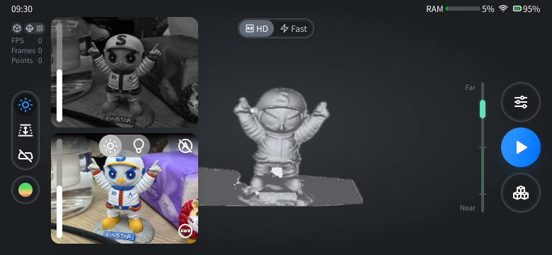
After entering the scan preview interface, you can adjust scanning settings for the current project.
Note
After start scanning, you can adjust the camera view or switch between data quality indicator and texture display, but you could not readjust the advanced settings.
Camera View
Col
Tap ![]() to enable camera view, it will show the black-and-white camera view and texture camera view (only shown when Acquire Texture is enabled).
to enable camera view, it will show the black-and-white camera view and texture camera view (only shown when Acquire Texture is enabled).
Col
-
Black-and-white camera:
 Auto-brightness is enabled by default (only supported for the fast scan mode). To switch to the
  manual mode, you can either tap the button in the upper right corner or the upper / lower part of the camera view, or use the left-side slider, and the brightness can be adjusted from 1 to 8 in this mode.
- The red points in the camera view indicate over-exposure points. To improve scan quality, it is recommended that you lower down the camera brightness when there are large areas of red over-exposure points, or increase the camera brightness when the camera view is too dark, until the brightness is proper, as shown in the figures below.
Col
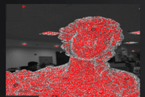 Brightness is too high
Col
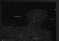 Brightness is too low
Col
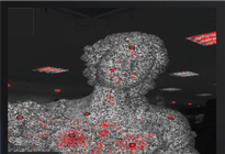 Brightness is proper
If you are not satisfied with the scanned texture, you can adjust settings as follows:
-
Texture camera:
- For adjusting the white balance: It is recommended that you first point the camera towards a white paper, a white wall or a white area on the calibration board before performing white balance calculation, then it will automatically calibrate the white balance (enabled by default when you choose Acquire Texture).
- When the environment light is too bright, you can:
- Use Auto-brightness (enabled by default);
- Tap the button or the upper / lower part of the camera view, or directly use the left-side slider to switch the status to , when you can use
 Camera light adjustment to manually adjust the texture camera light, and you can tap the lower part of the camera view or slide down the slider to decrease the brightness (down to 1).
- Use
- When the environment light is too dark, you can tap
 to switch to the LED supplement light adjustment (set as off by default), then you can tap the upper / lower part of the camera view or use the slider to manually adjust the brightness (0 ~ 5, 0 indicates the LED light is off), and when the brightness is above 0, the button status will be shown as
  .
.
Note
- Please perform
 white balance calculation before the scan if needed; this function is not supported after entering the scanning process.
 - If it prompts that "
 Unable to collect data", please adjust the distance of the scanner and the camera exposure status.
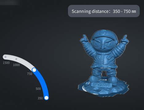
Scanning Distance (DOF)
Col
Tap  to enable the function for adjusting the scanning distance, and an arc slider and scan distance numerical prompt will appear:
- Drag the slider to adjust the scanning distance; the image outside the DOF range will not be generated into 3D data.
- Tap
 on the left side to exit this adjusting.
Col
Remove Base
Tap  to enable the Remove Base function, which will automatically identify the base plane and mask the scanning data below it during the scanning process (retaining any marker points, if present), helping you improve data processing efficiency.
- During the process of base auto-recognition, it will prompt that "Please point at the plane to be removed".
- Once the blue base plane appears in the model preview scene, if you confirm that it is the desired plane, then you can tap
 to start scanning.
Note
- The Remove Base function is disabled by default; once enabled, the identified base plane will be continuously displayed during the scanning preview and will be updated in real-time.
- During the scanning preview, you can toggle this function. However, once you officially start the scanning process, you cannot change this setting.
- If it prompts that "
 Base plane not recognized", please point the scanner towards the base plane of the target object.
 - If you are currently using the fast scan mode with marker alignment mode enabled, please ensure that the device's battery level is not below 30%.
Data Display Mode
Tap  to expand the list, and you can choose a data display mode:
 : Data Quality Indicator; enabled by default for non-texture scanning objects.
 : Texture Display; enabled by default when you choose Acquire Texture in
  Advanced Settings.
Note
You can enable only one of these two display modes; indicates that both modes are disabled.
Advanced Settings
Tap ![]() in the right-side function bar to open the Advanced Settings window, where you can preset the scanned model as Object or Portrait, and the corresponding Scan Configuration and Align Mode:
in the right-side function bar to open the Advanced Settings window, where you can preset the scanned model as Object or Portrait, and the corresponding Scan Configuration and Align Mode:
The introduction to different align modes:
- Feature alignment: It is suitable for objects that cannot place markers and have rich surface features. It automatically completes the alignment by the surface geometric features of the object to be scanned.
- Texture alignment: It is suitable for objects with rich texture patterns on the surface but lacking rich intricate geometric features. It utilizes the surface texture features of the scanned object to automatically complete the alignment and merging process.
- Marker alignment: It is suitable for objects with limited geometric features or for scenarios that require high accuracy. It automatically completes the alignment by using markers attached randomly to the flat surface of the scanned object; for the HD scan mode, markers of 3 mm and 6 mm can be recognized at the same time; for the fast scan mode, markers of 6 mm and 12 mm can be recognized.
-
Scan Configuration:
-
Resolution: Set the scanning resolution range (point distance) as low / medium (default) / high; the higher the resolution, the slower the Data Quality Indicator turns green, and the mesh data will be more precise.
Fast Mode:Resolution Scanning Distance (DOF) Point Distance Low 350 mm ~ 1500 mm 2.5 mm ~ 10 mm Medium 350 mm ~ 1000 mm 1.0 mm ~ 2.5 mm High 350 mm ~ 750 mm 0.5 mm ~ 1.0 mm HD Mode:
Resolution Scanning Distance (DOF) Point Distance Low 100 mm ~ 350 mm 0.5 mm ~ 3 mm Medium 100 mm ~ 300 mm 0.25 mm ~ 0.5 mm High 100 mm ~ 250 mm 0.1 mm ~ 0.25 mm -
Acquire Texture: Disabled by default; if disabled, the texture alignment mode can not be used, and
Texture overlay mode as well as texture mapping are also not available.
-
-
Align Mode:
- Feature alignment: Enabled by default; if enabled,
 will appear in the project information area in the upper left corner.
 - Texture alignment: Disabled by default; if enabled,
 will appear in the project information area in the upper left corner.
 -
Marker alignment: Disabled by default; if enabled,
 will appear in the project information area in the upper left corner:
- For the HD scan mode, you can use 3 mm and 6 mm markers for data alignment.
- For the fast scan mode, you can use 6 mm (supported for Medium / High Resolution) and 12 mm (supported for Low / Medium / High Resolution) markers for data alignment.
Note
For scanning large-scale objects with few geometric features, you can use 12mm markers to increase the scanning efficiency by placing less markers in the larger field of view.
- Feature alignment: Enabled by default; if enabled,
Note
- At least one alignment mode should be chosen.
- It is NOT recommended that you enable the feature alignment mode and the texture alignment mode simultaneously, otherwise it may impact the FPS.
- For scanning large-scale objects with both rich irregular geometric features and plain less geometric areas, you can enable the marker alignment mode and the feature alignment mode simultaneously.
- For scanning objects with rich repetitive regular geometric features (like car wheel) or pure plain areas with few geometric features, it is recommended that you only enable the marker alignment mode.
- For the fast scan mode, when the marker alignment mode is enabled:
- The texture alignment mode can not be enabled simultaneously.
- Only one size markers can be recognized in each scanning project.
- The brightness for the black-and-white camera can only be adjusted manually, and camera exposure function can not be used.
- Please ensure that the scanner has sufficient power (above 30%) during the scanning process, otherwise the scan can not be performed.
-
Scan Configuration:
-
Resolution: Set the scanning resolution range (point distance) as low / medium (default) / high; the higher the resolution, the slower the Data Quality Indicator turns green, and the mesh data will be more precise.
Fast Mode:Resolution Scanning Distance (DOF) Point Distance Low 350 mm ~ 1500 mm 2.5 mm ~ 10 mm Medium 350 mm ~ 1000 mm 1.0 mm ~ 2.5 mm High 350 mm ~ 750 mm 0.5 mm ~ 1.0 mm HD Mode:
Resolution Scanning Distance (DOF) Point Distance Low 100 mm ~ 350 mm 0.5 mm ~ 3 mm Medium 100 mm ~ 300 mm 0.25 mm ~ 0.5 mm High 100 mm ~ 250 mm 0.1 mm ~ 0.25 mm -
Acquire Texture: Enabled by default, and Texture alignment mode can be enabled, and
Texture overlay mode as well as texture mapping are also available.
-
-
Align Mode:
- Feature alignment: Enabled by default; if enabled, will appear in the project information area in the upper left corner.
- Texture alignment: Disabled by default; if enabled, will appear in the project information area in the upper left corner.
- Feature alignment: Enabled by default; if enabled,
Note
- At lease one alignment mode should be chosen.
- It is recommended that you only choose the feature alignment mode when scanning the face or body, and not choose the texture alignment mode at the same time.
- If you switch the object scan mode with marker alignment to portrait scan mode, the feature alignment mode will be enabled automatically.