Confirm Design Results
After the case is completed, you can review the classic design or AI design to confirm whether it meets your requirements. On the Design Case page, select the Waiting Confirm tab, click ![]() to view the model design in the case details, or click
to view the model design in the case details, or click ![]() to confirm the design result.
to confirm the design result.
Details
You can view the target tooth, total price, design type and design requirements of the case.
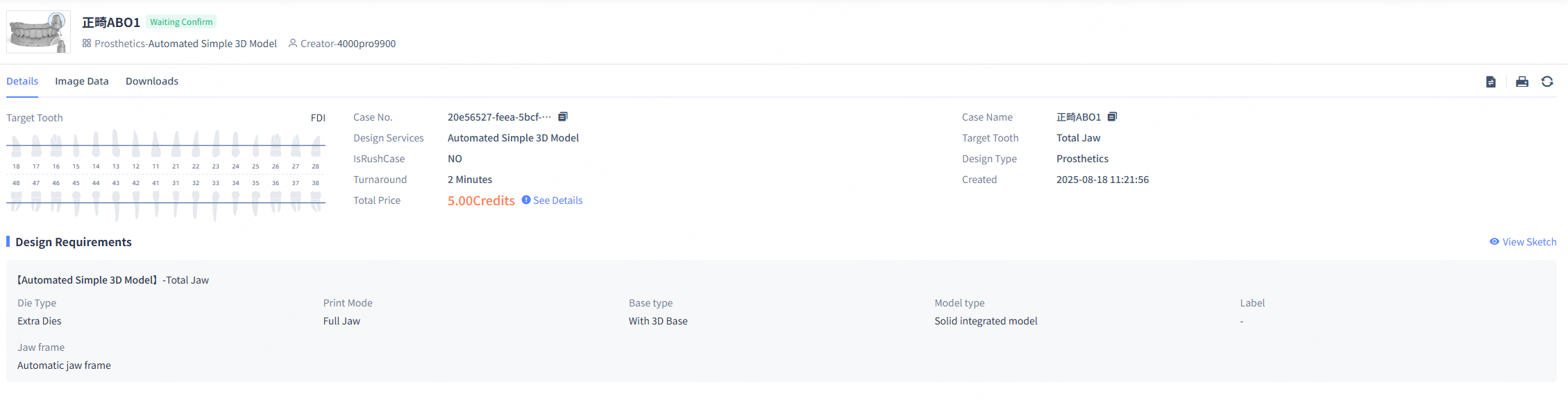
Image data
You can view the design result and the original model and use various tools to check if the design result meets the design requirements.
The model list is displayed on the left side where you can view the original model and the design result. You can click ![]() /
/![]() to show/hide the model.
to show/hide the model.
You can adjust the model's opacity by moving the slider.

Model editing
You can use the brush (![]() Form,
Form, ![]() Remove,
Remove, ![]() Smooth or
Smooth or ![]() Flatten) to edit the model.
Flatten) to edit the model.
- Click Data Trimming > Model Editing and select a editing tool. You can drag the slider below to adjust the brush radius and intensity until the brush size covers the area you want to modify.
- Hold the left mouse button and drag on the model to modify it.
Note
If margin line editing was previously performed, after model editing, margin line editing needs to be performed again.
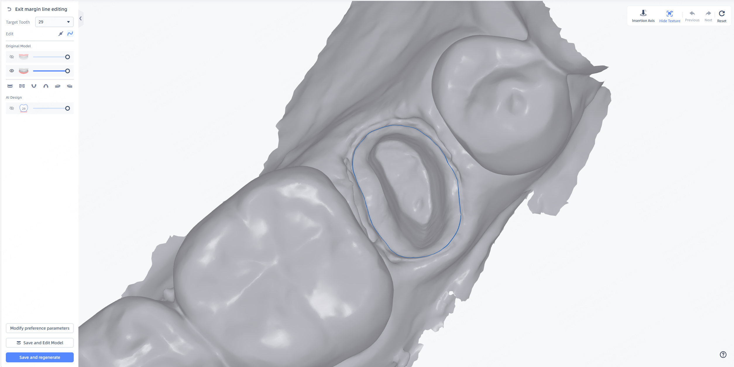
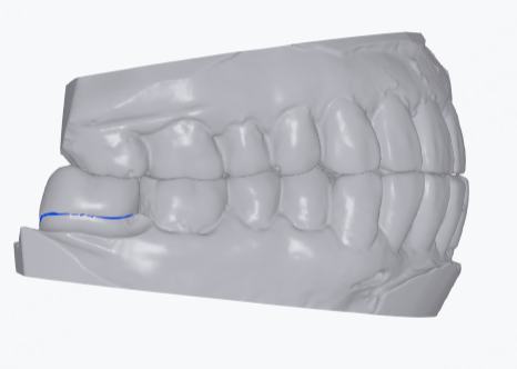
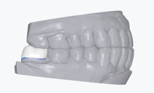
Margin line editing
The margin line wraps the range of the crown and editing the margin line changes the range of the crown. You can adjust the margin line to modify the range.
After entering margin line editing, the margin line will be automatically extracted.
-
In
 point control drawing mode, you can drag points on the edge line to adjust the edge line.
Note
- Click anywhere on the edge line to add a point.
- Hover the cursor over an editing point on the edge line and use the right mouse button or Delete key to delete the corresponding point.
-
In
 line control drawing mode, press and hold the left mouse button and move the mouse to directly draw the edge line.
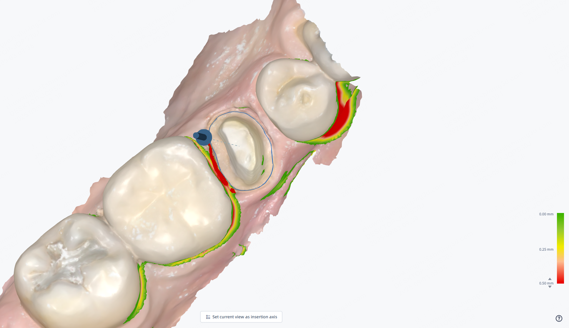
Insertion axis
The path of insertion refers to the direction in which the crown is seated. Different paths of insertion result in different undercut ranges.
Reset insertion axis
- Click Data Trimming > Insertion Axis.
- Move the blue arrow and the software will automatically reset the insertion axis according to the arrow direction. Or, you can rotate the model and click Set current view as insertion axis.
Note
This function is unavailable for Automated Simple 3D Models.
Form
You can use the brush (![]() Form,
Form, ![]() Remove,
Remove, ![]() Smooth or
Smooth or ![]() Flatten) to edit the crown surface.
Flatten) to edit the crown surface.
- In Crown Editing, click Form and select a editing tool. You can drag the slider below to adjust the brush radius and intensity until the brush size covers the area you want to modify.
- Hold the left mouse button and drag on the crown to modify it.

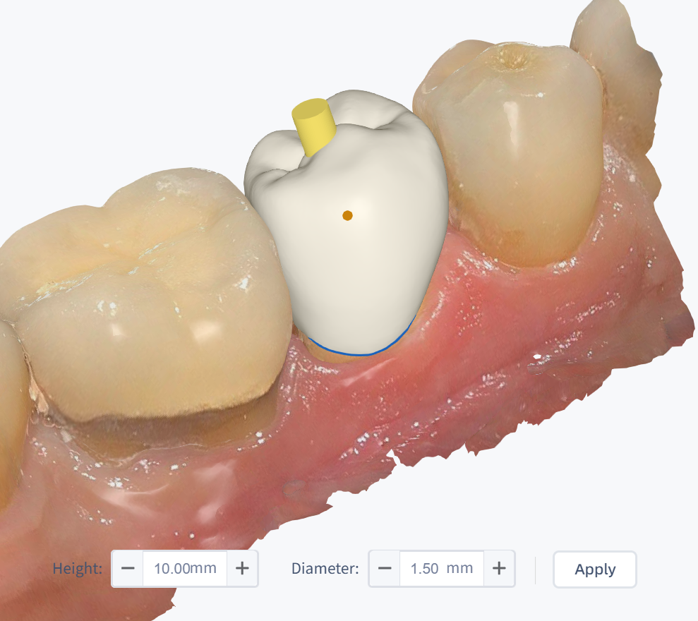
Screw Channel
For implant crowns, you can create a screw channel on the crown.
- In Crown Editing, click Screw Channel.
- A cylinder will appear on the model. Drag the dot to adjust the position of the screw channel; adjust the view angle, then drag the cylinder to adjust the direction of the screw channel.
- In the parameter bar below, you can enter or adjust the height and diameter of the screw channel.
- After adjustment, click Apply to generate the screw channel on the crown.
Note
- It is recommended to complete other edits of the crown (such as forming, remove, etc.) before creating the screw channel, as this operation cannot be modified after completion.
- The screw channel function is mutually exclusive with functions such as carving knife, thickness detection, and bite detection, and cannot be used at the same time.
- The crown editing function cannot be used again for a crown with a screw channel.
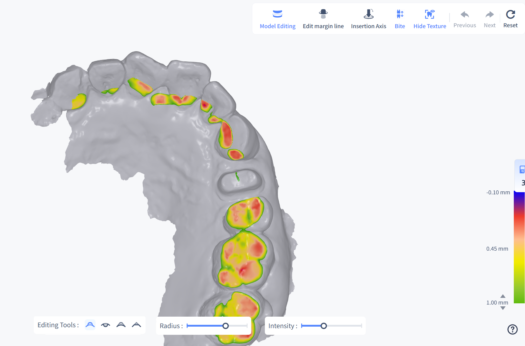
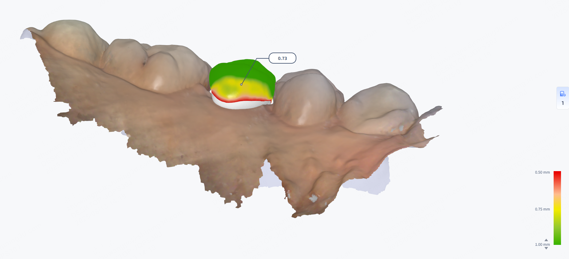
Thickness
Click Thickness to check the thickness of the AI design result. You can check the thickness by different colors shown on the model or a label of the specific value.
- Color indication: The model is colored to indicate the thickness. A color bar displayed in the bottom right corner shows the range of thickness.
- Specific value: Move the cursor to the colored areas and a label is displayed to show the specific value of thickness on this point.
Sectional
Click Sectional and a section will be automatically created on the model. The 2D window in the lower right corner shows the corresponding intersecting parts between the section and the model.
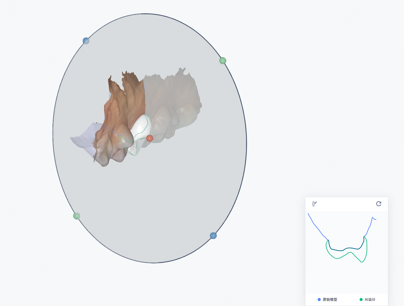
Section operations
- Move the section: Hold and drag the red ball at the center of the section to move it along the dental arch.
- Rotate section: Hold and drag the blue or green ball at the edge of the section to rotate it.
2D Window operations
- Free section: Click
 Free Section and you can draw a section on the model. Press and hold the left mouse button, then drag to draw a line to generate a section.
 - Zoom in/out: Scroll up and down the wheel to zoom in/out the sectional view.
- Measurement:
- Add a point: Click on the line to add a point.
- Move the point: Press the point and drag.
- Distance measurement: When 2 points are added, the distance between them will be shown on the 2D window, and a line linking the 2 points will be shown on the 3D model as well.
- Re-measurement: Add another 2 points to measure the distance again.
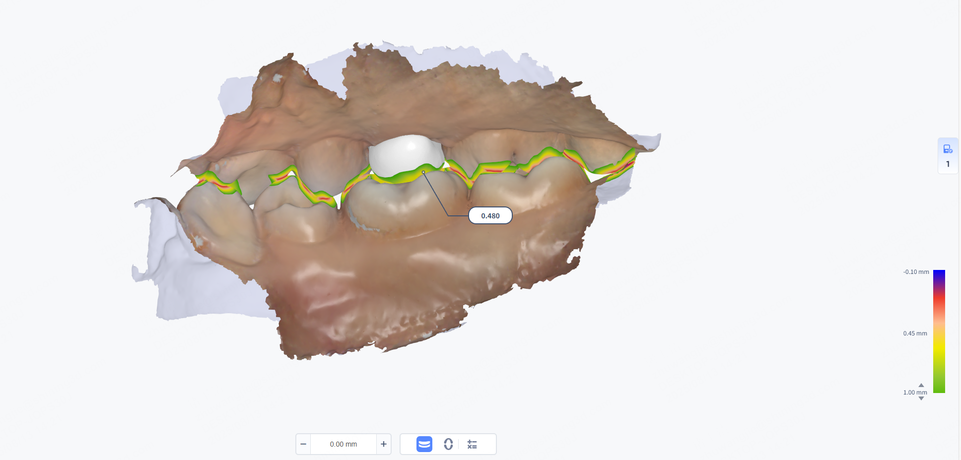
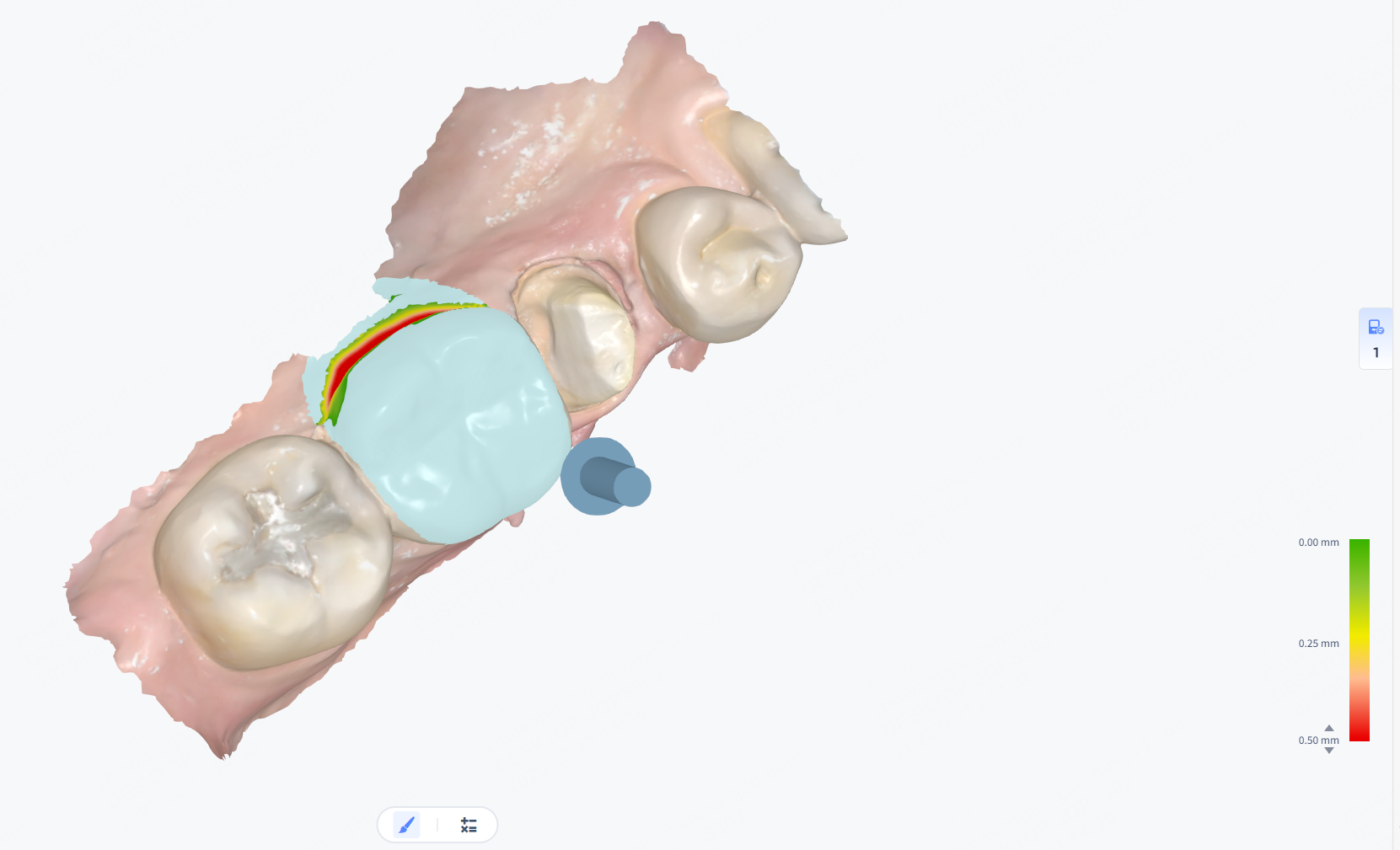
Bite
Bite is used to check the occlusal relationship of the upper jaw and the lower jaw. By detecting the collision depth of the jaws, you can judge whether the occlusion is correct. You can view occlusion depth by the color indication and specific values.
-
Color indication: The crown is colored to indicate the collision depth. A color bar displayed in the bottom right corner shows the range of the collision depth. Red indicates deep collision depth and green indicates shallow depth.
- Green: The separation area between the upper and lower teeth.
- Red: The collision area between the upper and lower teeth.
- Blue: The penetration area between the upper and lower teeth.
-
Specific value: Move the cursor to the colored areas on the crown and a label is displayed to show the specific value of collision depth on this point.
Undercut
Use the brush to mark the area to check for undercut and calculate the undercut value. Different colors on the model indicate undercut depth, and a color bar appears in the lower right.
Show/Hide texture
Col
 Hide texture
Col
 Show texture
Button Description
| Button | |
|---|---|
| Share to Dentist | Click this button to send the current design link to the dentist's email for review. |
| Redesign | Click this button to fill in issues with the current design and submit them to the designer; after submission, the current design case status will change to Paused. Note NoteOnly classic design cases support Redesign. |
| Compare the Design Results | When the case has two or more design results, click this button to compare any two different design results.Note Only classic design cases support Compare the Design Results. |
| Design Not Applicable | Click this button to cancel the design.Note Only AI design cases support design cancellation. |
| Credit Express Payment |