Alignment
Alignment tools can be used to adjust the spacial coordinates of the scanned data, so as to facilitate post-processing or reverse engineering.
On the right panel of measurement, click ![]() and an Align window will pop up on the left.
and an Align window will pop up on the left.
Note
You can import the un-meshed data in Measurement, align the data and return to the Scan step to update data changes.
Use precise coordinates to align the scanned data.
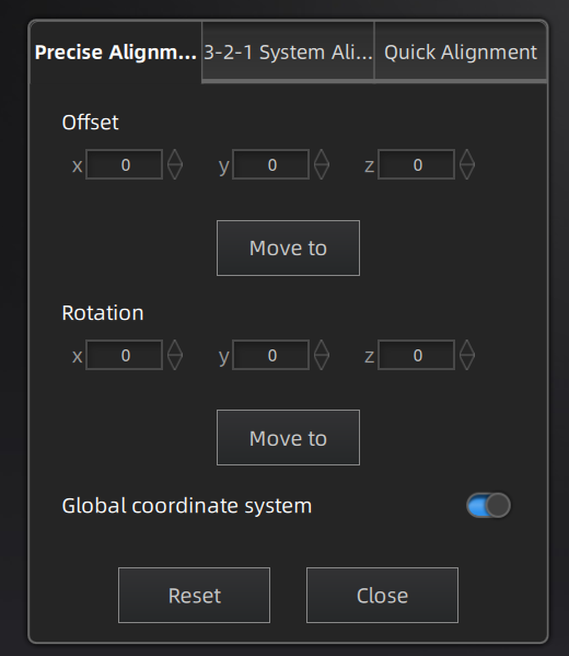
- Input value and adjust coordinates: Input values in Offset or Rotation, and click Move to to align model center with input coordinates and axis direction with rotation value.
- Adjust coordinates by the object mover tool: Hover the cursor on object mover tool. Once the object mover tool shines, hold Left Mouse Button or Middle Mouse Button to adjust the position and angle of model.
- Click Reset to cancel all movements in Precise Alignment.
- Click Close to save the movement and quit the alignment.
Note
The global coordinate system is disabled by default and needs to be enabled manually. Specifically, red points to positive X-axis, green points to positive Y-axis and blue points to positive Z-axis; if the global coordinate system does not appear on the interface, roll the mouse wheel to zoom out the model.
Use planes, lines and points as constraints to align the scanned data.
Note
Before alignment, you need to create feature points, lines, and planes, in which the feature line should not be perpendicular to the plane, or a window will pop up prompting failure.
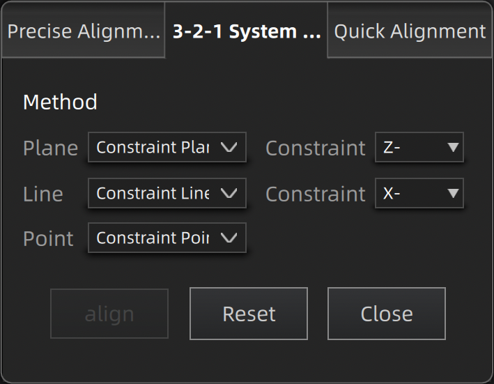
- Plane:Select a feature surface in the drop-down list, and select an axis in corresponding constraint drop-down list. The arrow on the plane corner indicates the positive direction of the plane, and the selected axis direction will be consistent with the plane direction.
- Line:Select a feature line in the drop-down list, and select an axis in corresponding constraint drop-down list. The arrow of the line indicates the positive direction of the line, and the direction of the selected axis will be consistent with that of the projection of the line on the selected plane.
- Point:Select a point in the drop-down list, of which the position is (0,0,0).
- Click Align to move coordinate axes. When the feature line is perpendicular to the plane, the movement fails and a window pops up prompting failure.
- Click Reset to cancel all movements.
- Click Close to save the movement and quit the alignment.
Note
About the global coordinate system, the red points to positive X-axis, green points to positive Y-axis and blue points to positive Z-axis; if the global coordinate system does not appear on the interface, roll the mouse wheel to zoom out the model.
Move the coordinate frame to align the scanned data.
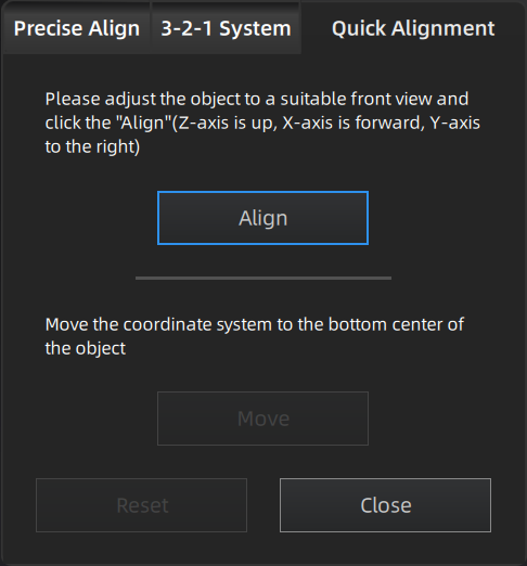
- Click Align and move the coordinate frame to the center of the object, with its X-axis perpendicular to the screen, Y-axis parallel to the screen and pointing rightward, and Z-axis parallel to the screen and pointing upward. The object remains its position.
- Click Move and move the coordinate frame to the bottom center of the object.
- Click Reset and restore the frame to its original state(before alignment).
- Click Close to save the model frame and close the dialog box.
Note
About the global coordinate system, the red points to positive X-axis, green points to positive Y-axis and blue points to positive Z-axis; if the global coordinate system does not appear on the interface, roll the mouse wheel to zoom out the model.