Scanning Settings
After entering the Scan step, you can set scanning parameters on the left side of the interface.
The scanning parameter settings for different scanning modes are different, and the introduction to settings for White Light Mode and IR Mode are as follows:
 White Light Mode
-
Camera Window
Preview the real-time image captured by the scanner camera so as to adjust the brightness of the camera accordingly.
-
Scan Mode
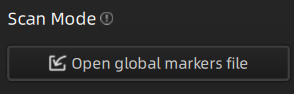
Hybrid alignment mode (including markers):
Click Open global markers file button to import local global markers file.
Note
- If you click Open global markers file button when a global markers file already exists in the current project, you will be prompted with a message "Are you sure to clear current data and rescan?".
- If you click Open global markers file button when there exists point cloud data, you will be prompted with a message "Are you sure to clear current data?".
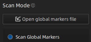
Global Markers alignment mode:
Click Open global markers file button to import local global markers file, or directly click Scan Global Markers and  optimize global markers.
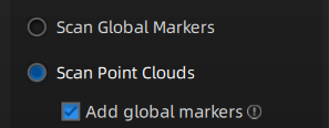
After switching to Scan Point Clouds, you can click Add global markers and new recognized markers can be added to global markers.
Note
- Add global markers switch can not be changed during the scanning process.
- If you click Open global markers file button when a global markers file already exists in the current project, you will be prompted with a message "Are you sure to clear current data and rescan?".
- If you click Open global markers file button or switch to Scan Global Markers, when there exists point cloud data, you will be prompted with a message "Are you sure to clear current data?".
- Newly recognized global markers will not be saved into the used global markers file during the Scan Point Clouds process.
-
Brightness
Drag the slider or use buttons on the back side of the scanner to adjust the brightness for different material or color of the object to get better scanning data. Please ensure that the object is clearly visible within the camera window and that there is no excessive red color displayed on the object.
Col
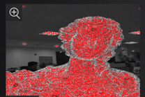
Brightness is too highCol
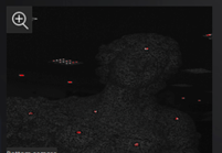
Brightness is too lowCol
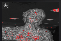
Brightness is normal -
Working Distance
According to different object size and alignment requirements, you need to drag the slider to adjust the working distance, namely effective area of the scanner.
The range of value is 200 mm ~ 700 mm; higher value means using longer working distance to get more data, but will lose some detail of the data.Note
Foot station alignment mode does not support this function.
-
Texture LED Light
It is recommended that you turn on the texture LED light when there is not enough light for better texture scanning.
Note
- Foot station alignment mode does not support this function.
- This function is available only when Texture scan is enabled.
- This switch cannot be changed during scanning.
-
Plane Detection
With this feature being enabled, the software will automatically detect and erase the plane where the object is located. This helps reduce the chances of misaligning planes or objects with distinct features.
Note
- Only Hybrid mode (with Features) supports this function.
- If you need to scan objects that are flat or have few features, it is recommended that you paste markers for helping alignment.
-
Data Quality Indicator
With this feature being enabled, the scanning data will be displayed in the form of quality chromatography.
- Green indicates high-quality scanning data at that location.
- Orange indicates low-quality scanning data at that location, indicating insufficient scanning. Further scanning is needed. Otherwise, insufficiently scanned data may disappear or display abnormally after data processing.
Note
By default, this feature is disabled for texture scanning, while it is enabled for other scanning modes.
-
Auto Cutting Plane
With this feature being enabled, during the scanning preview, the software will intelligently and in real-time identify the largest plane and mark it with a blue-green grid. The data below the marked plane will not be shown.
Note
The unique plane marked during the scanning preview can change in real-time. The plane marked as the last one at the end of the scanning preview will be considered. If the Cutting Plane feature is used, this feature cannot be used.
-
Adjust Point Distance
To modify the point spacing size for the current single project, you can drag the slider or click the up/down arrow buttons: the default value is set to the point distance when creating a project group.
Note
- If the number of projects in the current project group is greater than 1, this feature is not available.
- If the adjusted point distance is smaller than the original setting, it is recommended that you should modify the point distance based on the prompts in the pop-up window, or it may result in insufficient memory for generating the mesh model or point cloud.
 IR Mode
-
Camera Window
Preview the real-time image captured by the scanner camera so as to adjust the brightness of the camera accordingly.
-
Brightness
Drag the slider or use buttons on the back side of the scanner to adjust the brightness for different material or color of the object to get better scanning data. Please ensure that the object is clearly visible within the camera window and that there is no excessive red color displayed on the object.
Col
Brightness is too highCol
Brightness is too lowCol
Brightness is normal
-
Working Distance
According to different object size and alignment requirements, you need to drag the slider to adjust the working distance, namely effective area of the scanner.
The range of value is 200 mm ~ 700 mm; higher value means using longer working distance to get more data, but will lose some detail of the data. -
Texture LED Light
It is recommended that you turn on the texture LED light when there is not enough light for better texture scanning.
Note
- This function is available only when Texture scan is enabled.
- This switch cannot be changed during scanning.
-
Hair Mode
Enable this function to scan hair easier, but it could increase data noise.
Note
This switch cannot be changed during scanning.
-
Plane Detection
With this feature being enabled, the software will automatically detect and erase the plane where the object is located. This helps reduce the chances of misaligning planes or objects with distinct features.
Note
Only Hybrid mode (with Features) supports this function.
-
Data Quality Indicator
With this feature being enabled, the scanning data will be displayed in the form of quality chromatography.
- Green indicates high-quality scanning data at that location.
- Orange indicates low-quality scanning data at that location, indicating insufficient scanning. Further scanning is needed. Otherwise, insufficiently scanned data may disappear or display abnormally after data processing.
Note
By default, this feature is disabled for texture scanning, while it is enabled for other scanning modes.
-
Auto Cutting Plane
With this feature being enabled, during the scanning preview, the software will intelligently and in real-time identify the largest plane and mark it with a blue-green grid. The data below the marked plane will not be shown.
Note
The unique plane marked during the scanning preview can change in real-time. The plane marked as the last one at the end of the scanning preview will be considered. If the Cutting Plane feature is used, this feature cannot be used.
-
Adjust Point Distance
To modify the point spacing size for the current single project, you can drag the slider or click the up/down arrow buttons: the default value is set to the point distance when creating a project group.
Note
- If the number of projects in the current project group is greater than 1, this feature is not available.
- If the adjusted point distance is smaller than the original setting, it is recommended that you should modify the point distance based on the prompts in the pop-up window, or it may result in insufficient memory for generating the mesh model or point cloud.
-
Camera Window
Preview the real-time image captured by the scanner camera so as to adjust the brightness of the camera accordingly.
-
Scan Mode
Hybrid alignment mode (including markers):
Click Open global markers file button to import local global markers file.
Note
- If you click Open global markers file button when a global markers file already exists in the current project, you will be prompted with a message "Are you sure to clear current data and rescan?".
- If you click Open global markers file button when there exists point cloud data, you will be prompted with a message "Are you sure to clear current data?".
Global Markers alignment mode:
Click Open global markers file button to import local global markers file, or directly click Scan Global Markers and optimize global markers.
After switching to Scan Point Clouds, you can click Add global markers and new recognized markers can be added to global markers.
Note
- Add global markers switch can not be changed during the scanning process.
- If you click Open global markers file button when a global markers file already exists in the current project, you will be prompted with a message "Are you sure to clear current data and rescan?".
- If you click Open global markers file button or switch to Scan Global Markers, when there exists point cloud data, you will be prompted with a message "Are you sure to clear current data?".
- Newly recognized global markers will not be saved into the used global markers file during the Scan Point Clouds process.
-
Brightness
Drag the slider or use buttons on the back side of the scanner to adjust the brightness for different material or color of the object to get better scanning data. Please ensure that the object is clearly visible within the camera window and that there is no excessive red color displayed on the object.
Col
Brightness is too highCol
Brightness is too lowCol
Brightness is normal
-
Working Distance
According to different object size and alignment requirements, you need to drag the slider to adjust the working distance, namely effective area of the scanner.
The range of value is 200 mm ~ 700 mm (200 mm ~ 450 mm for medium objects); higher value means using longer working distance to get more data, but will lose some detail of the data.Note
Foot station alignment mode does not support this function.
-
Texture LED Light
It is recommended that you turn on the texture LED light when there is not enough light for better texture scanning.
Note
- This function is available only when Texture scan is enabled.
- This switch cannot be changed during scanning.
-
Plane Detection
With this feature being enabled, the software will automatically detect and erase the plane where the object is located. This helps reduce the chances of misaligning planes or objects with distinct features.
Note
- Only Hybrid mode (with Features) supports this function.
- If you need to scan objects that are flat or have few features, it is recommended that you paste markers for helping alignment.
-
Data Quality Indicator
With this feature being enabled, the scanning data will be displayed in the form of quality chromatography.
- Green indicates high-quality scanning data at that location.
- Orange indicates low-quality scanning data at that location, indicating insufficient scanning. Further scanning is needed. Otherwise, insufficiently scanned data may disappear or display abnormally after data processing.
Note
By default, this feature is disabled for texture scanning, while it is enabled for other scanning modes.
-
Auto Cutting Plane
With this feature being enabled, during the scanning preview, the software will intelligently and in real-time identify the largest plane and mark it with a blue-green grid. The data below the marked plane will not be shown.
Note
The unique plane marked during the scanning preview can change in real-time. The plane marked as the last one at the end of the scanning preview will be considered. If the Cutting Plane feature is used, this feature cannot be used.
-
Adjust Point Distance
To modify the point spacing size for the current single project, you can drag the slider or click the up/down arrow buttons: the default value is set to the point distance when creating a project group.
Note
- If the number of projects in the current project group is greater than 1, this feature is not available.
- If the adjusted point distance is smaller than the original setting, it is recommended that you should modify the point distance based on the prompts in the pop-up window, or it may result in insufficient memory for generating the mesh model or point cloud.