Foot Scanning
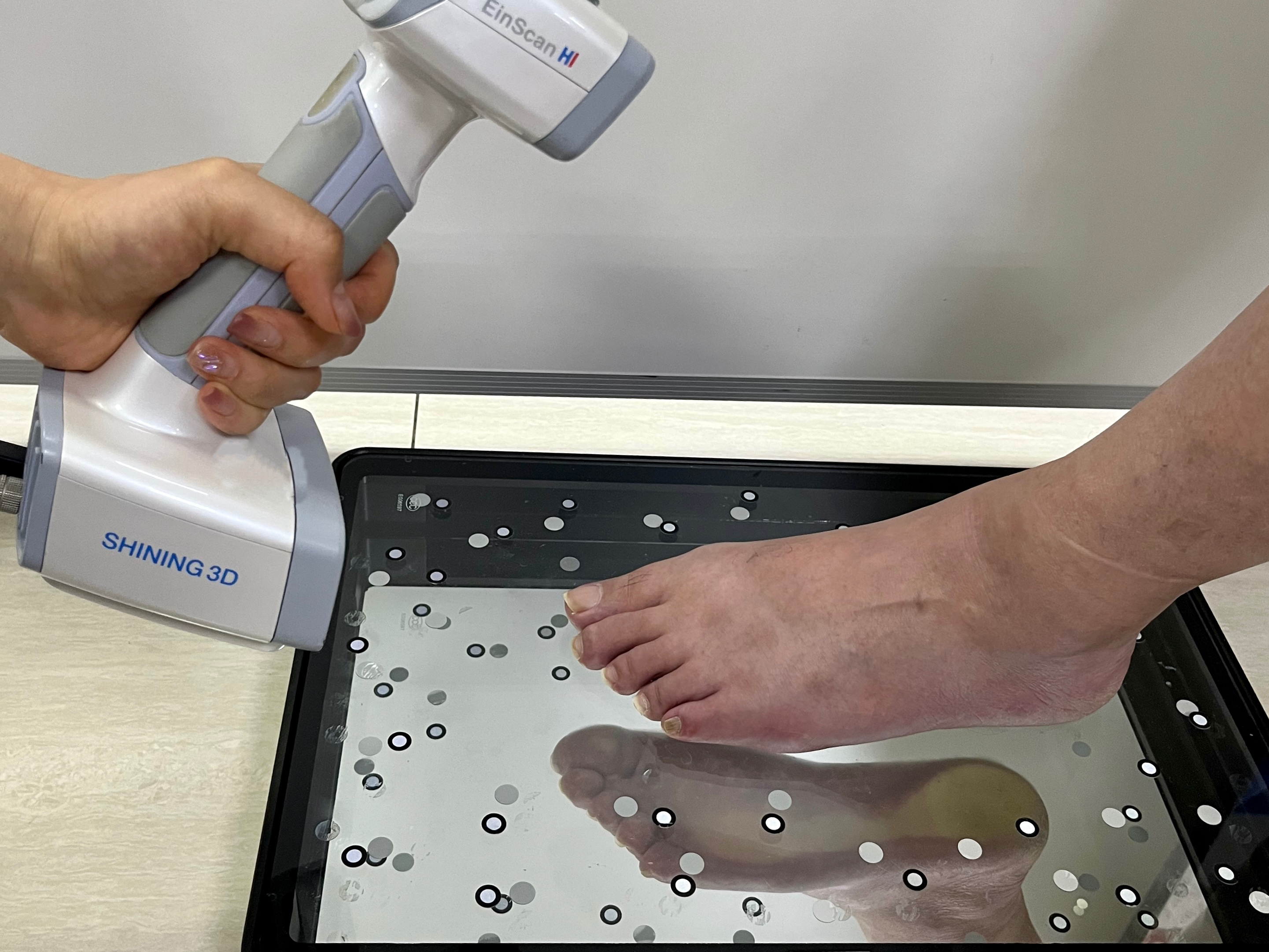
If you need to scan the feet, it is recommended that you use a glass foot station to assist in scanning the sole data, and utilize the specialized foot station alignment mode for foot scanning.
Caution
- It is recommended that you keep the surrounding environment clean and unobstructed before scanning.
- Please place the feet parallel to the long edge of the glass foot station and do not cover the markers.
- Please avoid scanning in environments with strong direct light above the foot station, as it may cause overexposure and affect speckle projection.
- Please ensure to scan all necessary data of the sole refracted on the bottom of the glass foot station to avoid impacting the alignment effect. It is recommended that you enable the data quality indicator during scanning, and scan until the green data is complete and without gaps.
Operation Steps
1.Create a new project group and select the scan mode as ![]() White Light Mode.
White Light Mode.
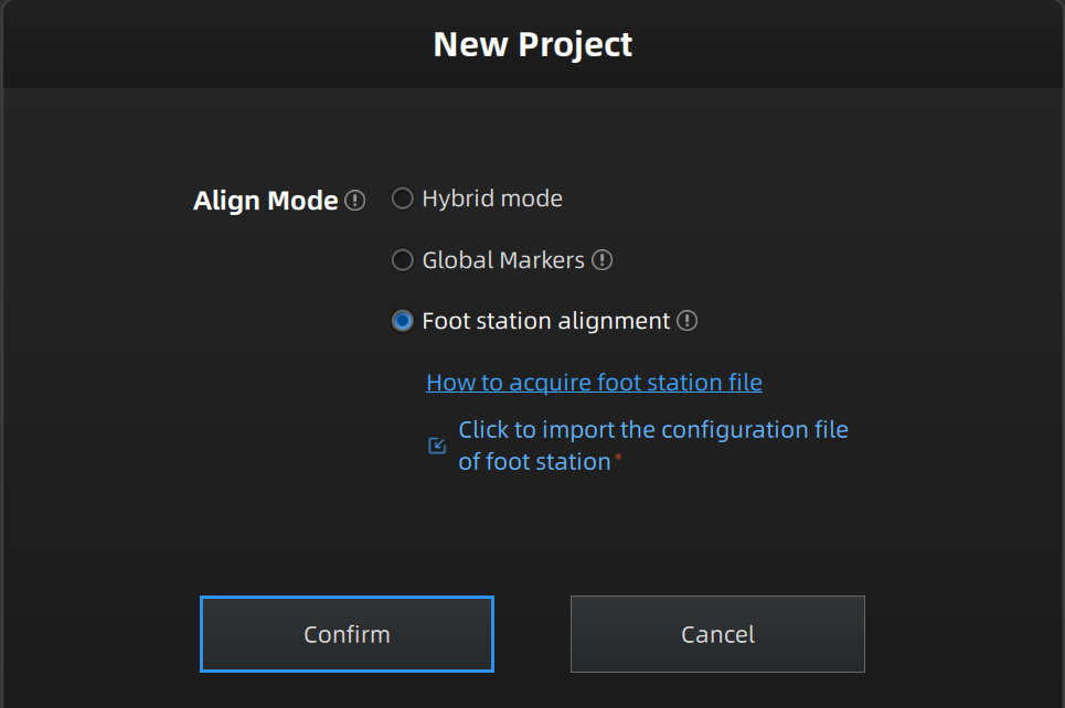
2.When setting the project, select Foot Station Alignment mode and ![]() import the configuration file (.p3) of foot station, and click Confirm to enter the foot scanning process.
import the configuration file (.p3) of foot station, and click Confirm to enter the foot scanning process.
Note
- Each foot station has its own configuration file; please log into Shining 3D Passport official website, enter serial number in the window of Bind More Products to complete binding, and download the configuration file in the interface of My Products.
- If it prompts "Please import the configuration file of the foot station".
- You can click
 button in the uploaded configuration file bar to delete the file.
3.Please place the left foot (default) according to the bottom left corner illustration on the Scan step interface; you can click Switch Right Foot button to switch to the right foot for scanning.
Note
During the pre-scan / scanning process or when there is scanned data but no point cloud generated, you cannot switch between left and right foot.
Col
Col
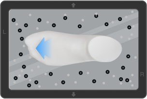
Left foot
Col
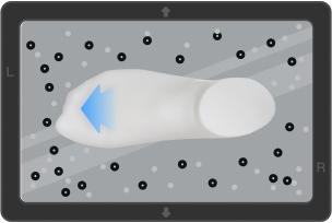
Right foot
Col
4.On the Step step interface, you can preview the real-time foot images captured by the scanner camera through the camera window, adjust the scanner brightness, switch data quality indicator function by scan settings; you can also use data editing toolbar to edit scanned foot data.
Note
For the instruction of menu of right mouse button and shortcuts, please see data editing.
5.After completing the scan, click ![]() Optimizing and Generating Point Cloud in the right-side function bar, and click
Optimizing and Generating Point Cloud in the right-side function bar, and click  Mesh the foot model.
Note
- Foot station alignment mode does not support generating the point cloud directly.
- Foot station alignment mode uses default settings for mesh, and can not be adjusted.
- For the instruction to the right-side function bar, please see data editing.
6.After mesh completes, you will be directed to the Post-Processing step for mesh editing.
Note
- If both left and right foot have been scanned,
 Two Feet model is displayed as default; you can click this button to switch to
  Left Foot and
  Right Foot.
 - For the instruction to data editing tools and right-side function buttons, please see data editing, foot station alignment mode does not support texture remapping and model display; additionally, when
 sharing data and
  exporting to third-party softwares, you can choose to share two feet, left foot or right foot model, and the former situation supports multiple choices.
 - If the data of displayed model on the current Post-Processing step interface is not scanned but imported, the recognition of left or right foot is not supported.
7.After completing post-processing, you can click  in the right-side function bar to save data locally.
Note
You can choose to save two feet, left foot or right foot model, and support multiple choices.
8.(Optional) Support measuring the point cloud data of the scanned foot.