Save
After coordinates alignment and click Continue, the software will direct you to the Save interface, where you can check the scanned model and save the model.
Besides, you can click Advanced Settings to find more settings for mesh optimization.
Note
The saving format for model files varies across different scanning modes. For more, please refer to the table.
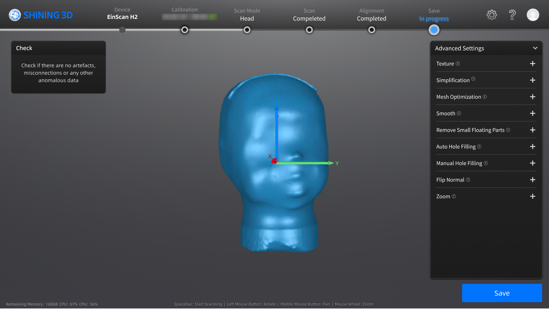
The operation steps are as follows:
-
Check if there is any anomalous data on the model.
-
(Optional) Use advanced settings to optimize the generated mesh.
Function Description Instructions Texture Brightness and Contrast can be adjusted.
Drag the slider or click the page up / down arrow to set the value from -100 to 100. The default is 0, indicating no adjustment.- Only project files that exclusively contain textures are accessible to this function.
- Click
 to reset the texture.
 - Click Confirm to confirm and save. This action is irreversible.
- Click Cancel to restore and exit.
Simplification Simplify the model data as the triangular mesh generated from the scan is in a large size.
Drag the slider or click the page up / down arrow to set the ratio from 1 to 99. The default is 0, indicating no simplification.- Over-simplification will result in the loss of data details.
- Click to reset the value to default.
- Click Preview to preview.
- Click Confirm to confirm and save. This action is irreversible.
- Click Cancel to restore and exit.
Mesh Optimization Restructure the mesh topology based on the mesh curvature and sharpen the surface features of scan data.
Drag the slider or click the page up/down arrow to set the ratio from 1 to 100. The default is 0, indicating no optimization.- The optimization duration varies depending on the amount of data.
- Click to reset the value to default.
- Click Preview to preview.
- Click Confirm to confirm and save. This action is irreversible.
- Click Cancel to restore and exit.
Smooth Smooth the possible noise on the surface of the scan data.
Drag the slider or click the page up / down arrow to set the ratio from 1 to 100. The default is 0, indicating no smoothness.- Click to reset the value to default.
- Click Preview to preview.
- Click Confirm to confirm and save. This action is irreversible.
- Click Cancel to restore and exit.
Remove Small Floating Parts Delete any small parts of data that are not connected to the main data.
Drag the slider or click the page up / down arrow to set the ratio from 1 to 100. The default is 0, indicating no removal.- Click to reset the value to default.
- Click Preview to preview.
- Click Confirm to confirm and save. This action is irreversible.
- Click Cancel to restore and exit.
Auto Hole Filling After selecting the hole filling type and entering the perimeter (mm), and holes within the specified perimeter will be filled automatically; the default value is 80, and the range is 10 ~ 100000.
You can delete unwanted neighboring areas to delete edge noise data; the default value is 3, and the range is 0 ~ 10 (0 indicates no neighboring area deleted).
Hole filling types: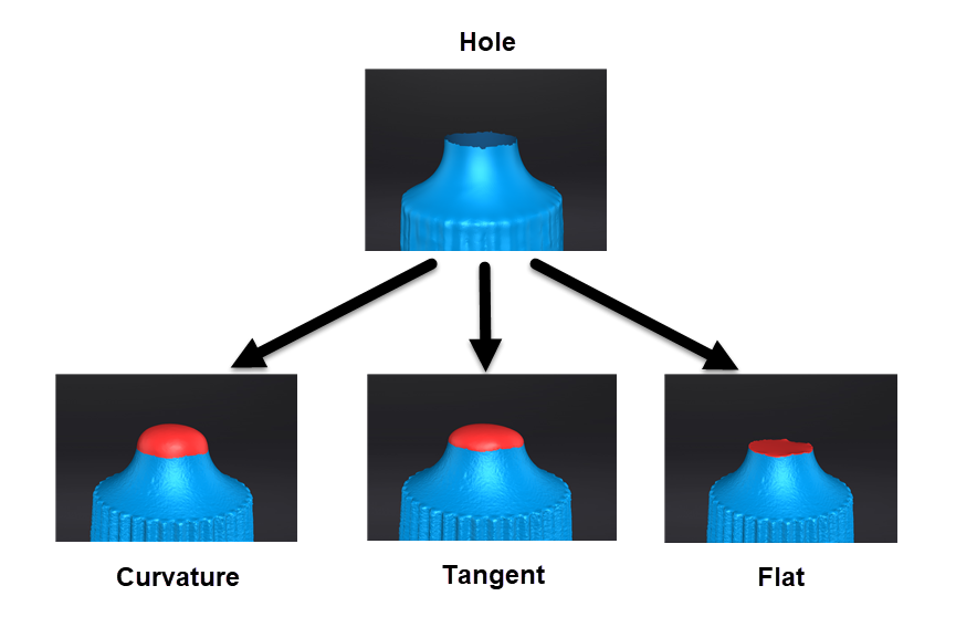
- The settings for Delete unwanted neighboring areas will be applied to all filled holes.
- Click Reset to reset the value to default, and the deleted edge data will also be restored.
- Click Preview to preview.
- Click Confirm to confirm and save. This action is irreversible.
- Click Cancel to restore and exit.
Manual Hole Filling After entering the manual hole filling mode, the hole edges will be displayed in green and get red after being picked. The number of the holes and the number of holes filled will be displayed on the interface.
Select filling types before picking a hole and then click the edges to perform filling actions.
You can delete unwanted neighboring areas to delete edge noise data; the default value is 3, and the range is 0 ~ 10 (0 indicates no neighboring area deleted).- The post-processing data needs to be saved manually.
- Click Reset to reset the value to default, and the deleted edge data will also be restored.
- Click Confirm to confirm and save. This action is irreversible.
- Click Cancel to restore and exit.
Flip Normal To redefine the front direction of the scanned data in reversal design.
Hold Shift+left mouse button to select areas to be flipped.- Default is to flip the entire dataset if no flip areas is selected.
- Click Preview to preview.
- Click Confirm to confirm and save. This action is irreversible.
- Click Cancel to restore and exit.
Zoom Adjust the scaling ratio of the model.
The default value is 100, indicating no zoom.- Click to reset the value to default.
- Click Preview to preview.
- Click Confirm confirm and save. This action is irreversible.
- Click Cancel to restore and exit.
-
Click the Save button in the bottom right corner to save the model.
The sizes and formats of saved data for each scanning mode are shown in the table below:
Scan Mode Maximum File Size Data Format Cranial 5 MB STL Face 6 MB OBJ / STL Upper Limb 7 MB OBJ / STL Torso 9 MB OBJ / STL Lower Limb 7 MB OBJ / STL Foot No limit STL Socket 9 MB OBJ / STL Seating 7 MB STL Note
Model files that exceed the data size limit will be automatically compressed when being saved.