Data Editing
When you start scanning, you can edit the scanned data in the Scan step to clean up and finalize the data before generating the mesh model.
Data Editing Toolbar
You can use following tools to edit data after the scanning paused.

Note
- After editing the data, you can continue scanning to acquire more data.
- If necessary editing operations have been performed on the scanned data, please click
 to apply the edits before generating the mesh model.
| Icon | Function | Description |
|---|---|---|
| Orthogonal View | The object does not appear larger when closer, and smaller when farther away; also known as "isometric view", the size of the object displayed in the view is independent of the current viewpoint distance. | |
 |
Multi View | Observe the scanned data from |
 |
Cutting Plane | Create a Cutting Plane to do quick cut and can be used for blocking scanning. |
| Point Cloud Edit | In this mode, a point cloud is chosen. Click it again and you can switch to the Edit Markers mode.(This mode is enabled by default if there is a point cloud.) Note Note
|
|
| Edit Markers | In this mode, the selection tool is used to only select markers data. Clicking this button again will switch to the Point Cloud Edit mode (assuming there is point cloud data available), and by default, this button is in Point Cloud Edit mode.Note
|
| Icon | Function | Description |
|---|---|---|
| Rewind | To select (highlighted in red) the scanning data corresponding to a specific frame, drag the progress bar. Click Confirm to delete the corresponding data; click Exit to exit rewind. NoteUp to 200 frames of data can be rewound; and you can rewind multiple times until the first frame of this scan. |
|
 |
Rectangular | Select or deselect a rectangular area. |
 |
Polygon | Select or deselect a polygon area. |
 |
Lasso | Select or deselect the area by using the lasso tool. |
 |
Straight Line | Move the cursor to draw a straight line to select or deselect the area. |
 |
Brush | Select or deselect the area by using the brush. Hold down Shift or Ctrl, and at the same time, roll the mouse wheel will scale the brush size. |
 |
Select All | Select all of the data. |
 |
Unselect | Cancel all the selections. |
 |
Connected Domain | Click the button after selecting data, all connected region to the selected data will be selected. |
 |
Revert | Revert the selection. |
 |
Delete | Click the the button or use Del to delete the selected data. |
| Icon | Function | Description |
|---|---|---|
 |
Undo | Undo the last deletion and recover the last deleted data. Multiple deletions can be undone by clicking multiple times. |
| Redo | Redo the last operation and recover the last operation data. Multiple operations can be redone by clicking multiple times. |
|
 |
Cancel | Undo all edits, and exit edit mode. |
 |
Apply | Click the button or space bar to apply the edit, and exit edit mode. |
Side Function Bar
You can use more functions on the right panel in Scanning.
| Icon | Function | Instruction |
|---|---|---|
 |
Clean Data | Clean the current point cloud data to redo scan. |
Context Menu
| The function is the same as the function on the toolbar, and can be operated by shortcut keys. | |
| Connected Domain | Click the button after selecting a patch of data and all connected region to the selected data will be picked; can be operated by shortcut keys. |
| The data on the interface is displayed in the center according to the appropriate size; can be operated by shortcut keys. | |
| The rotation center can be set on the data by Left Button; can be operated by shortcut keys. | |
| After reset, the center of rotation is at the data center. | |
| Click to hide or show the cutting plane (if has been set). | |
| Ticked by default, and can be cancelled to close the left Camera window. | |
| With this option being ticked, a second Camera window will show at the left side. |
Shortcut
Cutting Plane
If you need to remove the object's base data during the scanning process, Cutting Plane can be a very effective tool.
By setting up a cutting plane, the data below the plane will not be captured.
Note
A cutting plane can be set up after opening a global markers file or scanning global markers, and can be saved while saving the global markers.
Create a Cutting Plane
Three methods to create a cutting plane are shown in the table as follows:
| Method | Description |
|---|---|
| Fitting Point Cloud | Hold Shift+Left Button to select the point cloud data, and click Create Plane. |
| Creating Straight Line | Hold Shift+Left Button to draw a line, and click Create Plane. |
| Markers | Hold Shift+Left Button to elect at least three markers, and click Create Plane. |
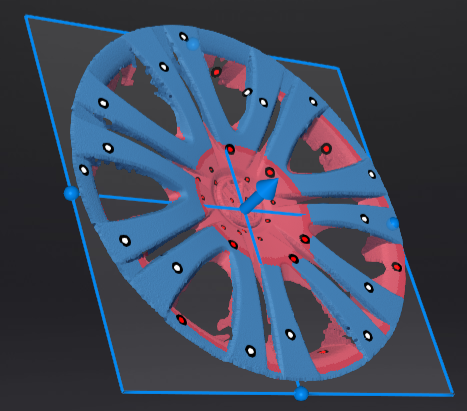
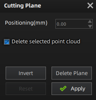
Edit the Cutting Plane
Col
- Delete the selected point cloud data or markers: When ticked, the selected point cloud data or markers will be highlighted in red. Apply the edit to delete the highlighted point cloud data or markers.
- Invert: Use this button to reverse the selection of data by flipping the cutting plane.
- Delete plane: Clicking this button will delete the current cutting plane and return to the interface for creating a new cutting plane.
- Reset: Reset all the operations performed after creating the cutting plane.
- Apply: Apply all the edits made.
Col
Note
- It is not supported to deleted all point cloud data.
- At least four markers should be remained at the front appearance of the cutting plane.
Col
- Translate the cutting plane: after generating the plane, you can enter numbers in the editing box or drag the arrow of the cutting plane's normal
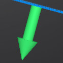 to translate the cutting plane.
 - Rotate the cutting plane: you can drag any of the four small balls on the edges of the cutting plane
 to rotate the cutting plane along a certain direction.
Col