Scan Settings
Before, during, and after scanning, you can set different parameters. For detailed information, please refer to scanning workflow.
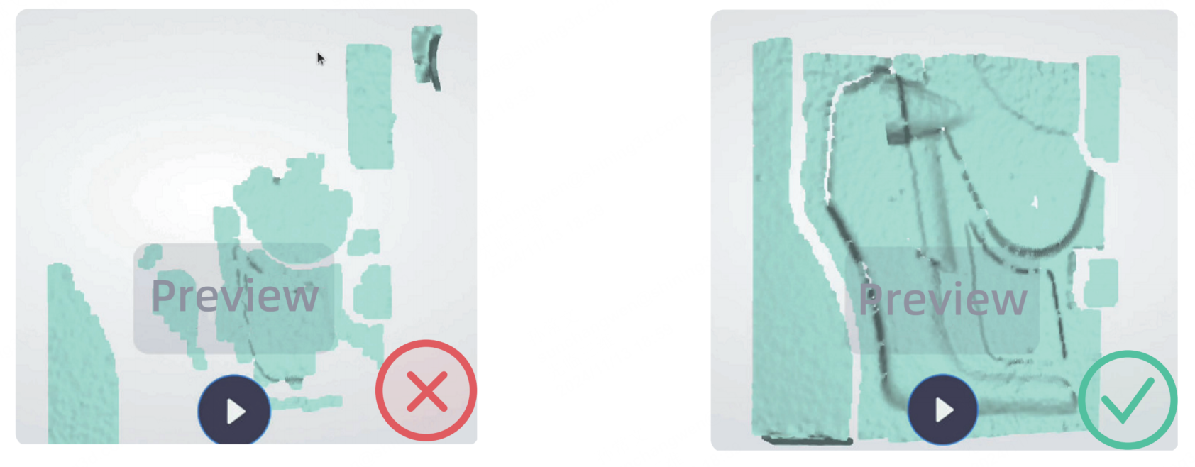
During the preview, you can check the quality of the scanning data and adjust parameters based on the displayed results.
Col
Col
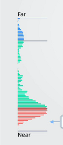
- Indicate working distance between the scanner and the object.
- Green: proper
- Red: too close and the screen border is also displayed in orange color.
- Blue: too far and the screen border is also displayed in blue color.
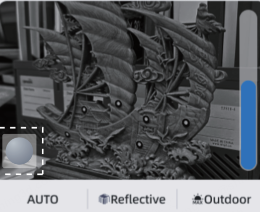
Move the scanner to an appropriate distance (Scan Distance Indicator shows most in green), and you can adjust the brightness by sliding the brightness level in the camera window. During the adjustment, you can check if the data in the view window is fully visible.
Note
-
 is used to adjust the brightness of the stereo cameras; this brightness level, which influences the amount of data that can be scanned, is crucial for the scanning process. If you want to adjust the brightness of the texture data, you can tap
  to switch to the texture camera brightness adjustment window.
 -
You can also tap AUTO to enable auto exposure. After that, it will automatically adjust exposure according to the object's color.
-
It is recommended to enable Reflective when scanning the reflective objects.
- It is recommended to enable Outdoor when scanning outdoors.
- After creating a new project with texture enabled or texture alignment activated, you can adjust the texture camera's exposure by sliding the bar in the texture camera window (tap ) to achieve the optimal effect.
- When the texture camera is turned on, it is recommended that you complete the white balance calibration according to the guide before scanning. You can place the calibration board on a horizontal flat surface with its back site (white) lying towards up or directly scan the white wall for white balance.
Note
When you adjusting the texture brightness or changing the scanning environment, it is recommended to white balance.
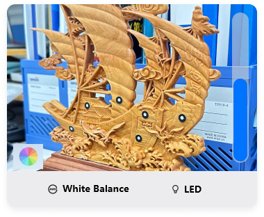
- Tap to show the texture camera. When the outdoor mode is enabled, the LED will be automatically turned off; when the outdoor mode is disabled, the LED will be automatically turned on.
- If the object surface is dark or reflective, increasing the scanning brightness or enable reflective mode recommended.
Data Quality Indicator
It is used to inspect the quality of the scanned model based on the color map, which is only available before meshing.
Range Indicator Box
When the Range Indicator Box is enabled, the scanner will project a green box and center point onto the objects to show the scan area when using invisible IR light mode.
Plane Detection
Plane detection can reduce the data misalignment.
When you choose either Feature Alignment or Hybrid Alignment, the Plane Detection option is enabled by default and displayed on the screen.
Caution
It is not recommended that you enable this feature when scanning objects with minimal texture details, as it may compromise scanning quality.
Alignment Mode
You can change the alignment mode if there is no scanned data.
Marker Size
During the scanning process, only the marker diameters that have been selected can be recognized, while any unselected diameters are ignored. In IR Rapid or IR Adaptive mode, it supports 6 mm and 12 mm. In laser HD mode, it supports 3 mm, 6 mm and 12 mm.
Change data collection distance range to filter out background or get maximum data amount.
Adjusting Resolution
Tap ![]() to open the settings window.
1. You can tap
to open the settings window.
1. You can tap ![]() /
/ ![]() /
/ ![]() to quickly switch the resolution.
to quickly switch the resolution.
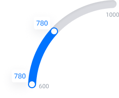
- Tap the screen and slide the arc ruler to accurately adjust the resolution.
Note
- If you modify the resolution of a project file in a project group, all project files within the same scanning mode (Rapid/HD mode) of the project group will have their resolution adjusted accordingly.
- If you increase the resolution, please ensure that the available memory space is greater than 15 GB.
- During the scanning, you can adjust the resolution. However, once the mesh generation are completed, you cannot adjust the resolution anymore. You can tap Scan in the lower-left corner or
 of the screen to go back to scan, and change the resolution and generate the mesh again, which will overwrite the previous mesh data.
 - The project file stores the latest scan data and mesh data.
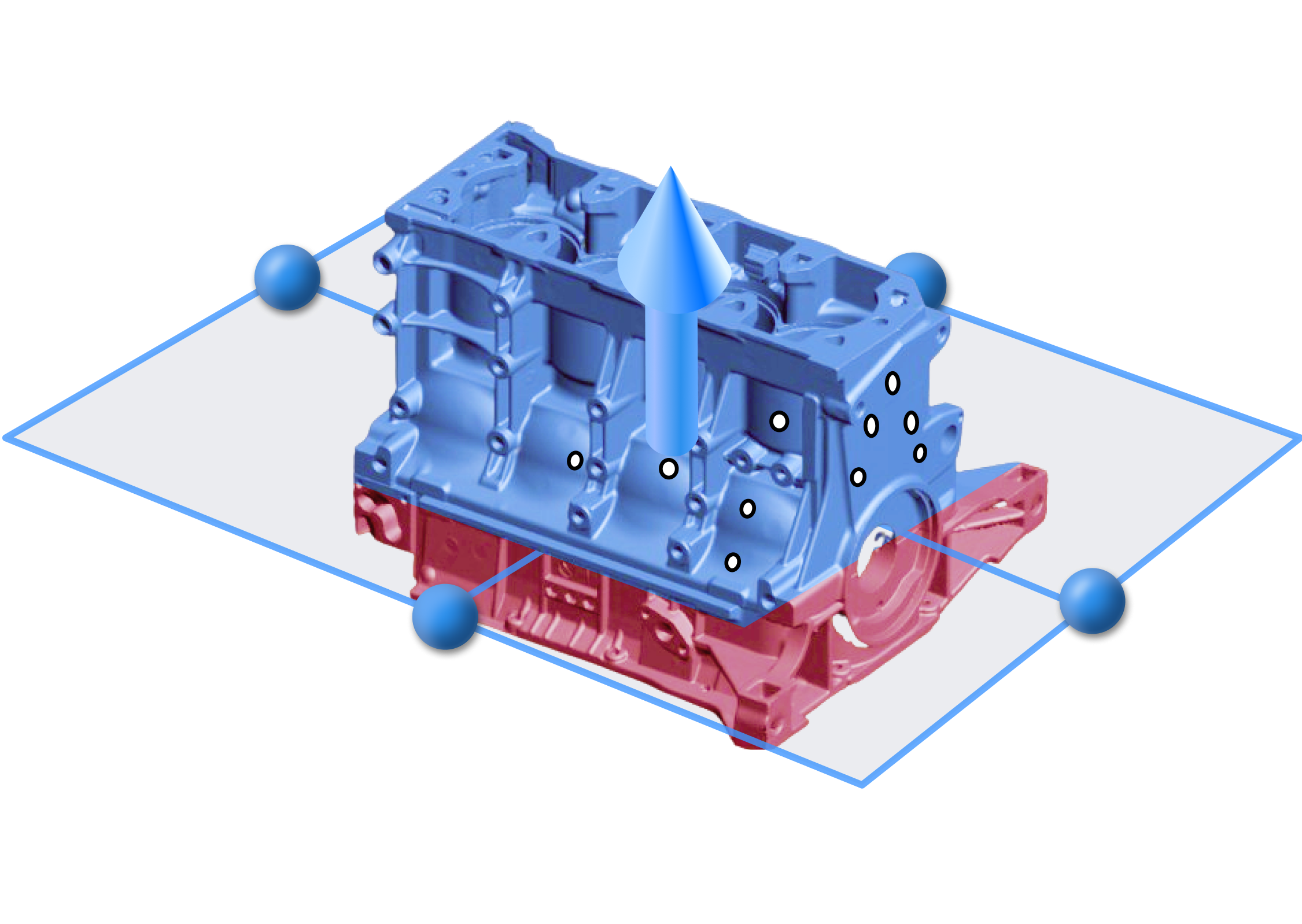
Create cutting plane
Tap ![]() to open the create cutting plane window.
to open the create cutting plane window.
-
You can switch selection between Point Cloud and Markers.
Note
Require 3 or more markers to create a cutting plane.
-
Tap Select to enable, and slice model data to select data.
- Tap Create to create a cutting plane.
- Tap Exit to undo the operations and return to the scan page.
- Unwanted data, marked in red, can be deleted by tapping Apply.
- Click and drag
 to manipulate the angles of the cutting plane, and click and drag
  to move the cutting plane. Once created successfully, no new data will be added below the cutting plane.
Edit Cutting Plane
Tap on the created cutting plane to enter the editing mode. Tap on any other area to exit the cutting plane editing mode.
| Task | Operation |
|---|---|
| Move cutting plane | Move the cutting plane by operating the active bar and dragging the arrow. |
| Rotate cutting plane | Cutting plane can be rotated around the axis by dragging the small ball. |
| Invert | Tap |
| Delete the plane | Tap |
When texture is enabled, you can view the real colors of the scanned object.
Note
When using texture alignment, texture is enabled by default.