Align
After scanning some data, you can click Measurement on the navigation bar, import the data, and select the data to carry out Align and so on.
On the right panel of Measurement, Click ![]() and a Align window will pop up on the left.
and a Align window will pop up on the left.
Note
You can import the un-meshed data in Measurement, align the data and return to scan to update data changes.
Caution
-
Alignment will not affect the shape or accuracy of the data.
-
Once you align the model to a new position and quit the alignment, you have to reload the file to restore previous position.
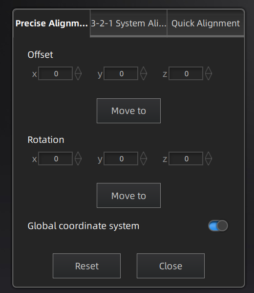
Input value and adjust coordinates
Input values in Offset or Rotation, and click Move to to align model center with input coordinates and axis direction with rotation value. Note
Note
Global coordinate system (disabled by default and need to be enabled manually) is the coordinate system on the right,in which red points to positive X-axis, green points to positive Y-axis and blue points to positive Z-axis; if the global coordinate system does not appear on the interface, roll the mouse wheel to zoom out the model.
Adjust coordinates by the object mover tool
Hover the cursor on object mover tool. Once the object mover tool shines,long press Left Mouse Button or Middle Mouse Button to adjust the position and angle of model.
Click Reset to cancel all movements in Exact Alignment.
Click Close to save the movement and quit the alignment.
3-2-1 Coordinate System Alignment (Plane-Line-Point Alignment) align data by choosing line and plane constraints. Before alignment, you need to create feature points, lines, and planes, in which the feature line is not perpendicular to the plane.
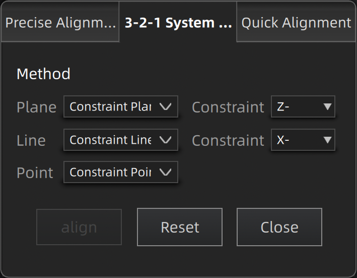
- Plane:Select a feature surface in the drop-down list, and select an axis in corresponding constraint drop-down list. The arrow on the plane corner indicates the positive direction of the plane, and the selected axis direction will be consistent with the plane direction.
- Line:Select a feature line in the drop-down list, and select an axis in corresponding constraint drop-down list. The arrow of the line indicates the positive direction of the line, and the direction of the selected axis will be consistent with that of the projection of the line on the selected plane.
- Point:Select a point in the drop-down list, of which the position is(0,0,0).
NoteGlobal coordinate system (disabled by default and need to be enabled manually) is the coordinate system on the right,in which red points to positive X-axis, green points to positive Y-axis and blue points to positive Z-axis; if the global coordinate system does not appear on the interface, roll the mouse wheel to zoom out the model.
Click Align to move coordinate axes. When the feature line is perpendicular to the plane, the movement fails and a window pops up prompting failure.
Click Reset to cancel all movements.
Click Close to save the movement and quit the alignment.
You can rotate the model to a wanted posture and a coordinate frame will show up.
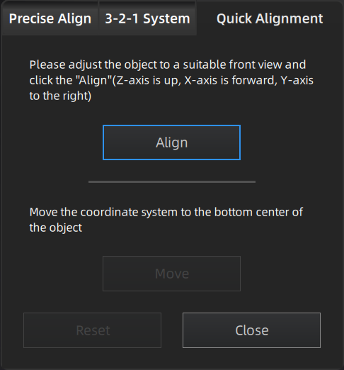
- Click Align and move the coordinate frame to the center of the object, with its X-axis perpendicular to the screen, Y-axis parallel to the screen and pointing rightward, and Z-axis parallel to the screen and pointing upward. The object remains its position.
- Click Move and move the coordinate frame to the bottom center of the object.
- Click Reset and restore the frame to its original state(before alignment).
- Click Close to save the model frame and close the dialog box.
Note
You can re-adjust the posture and align the model again if the alignment is not satisfactory.