Mesh Editing
After meshing model, you can perform mesh editing,data editingand use some other functions.
Mesh Editing
In the Mesh Editing window on the left side of the interface, click + to unfold the function panel.
Note
If the software version is V4.0.0.8 or above, you can click Preview to preview; or you can click Apply to preview.
| Texture | Brightness and Contrast can be adjusted. | Only project files that exclusively contain textures are accessible to this function. |
| Simplification | Simplify the model data as the triangular mesh generated from the scan is in a large size. Drag the slider or click the page up/down arrow to set the ratio from 1 to 99. The default is 0, indicating no simplification. |
|
| Mesh Optimization | Restructure the mesh topology based on the mesh curvature and sharpen the surface features of scan data. Drag the slider or click the page up/down arrow to set the ratio from 1 to 100. The default is 0, indicating no optimization. |
|
| Smooth | Smooth the possible noise on the surface of the scan data. Drag the slider or click the page up/down arrow to set the ratio from 1 to 100. The default is 0, indicating no smooth. |
|
| Remove small floating parts | Remove small floating parts in the scan data. Drag the slider or click the page up/down arrow to set the ratio from 1 to 100. The default is 0, indicating no removal. |
|
| Auto Hole Filling | After selecting the hole filling type, enter the perimeter. Holes within the specified perimeter will be filled automatically. | Hole filling types: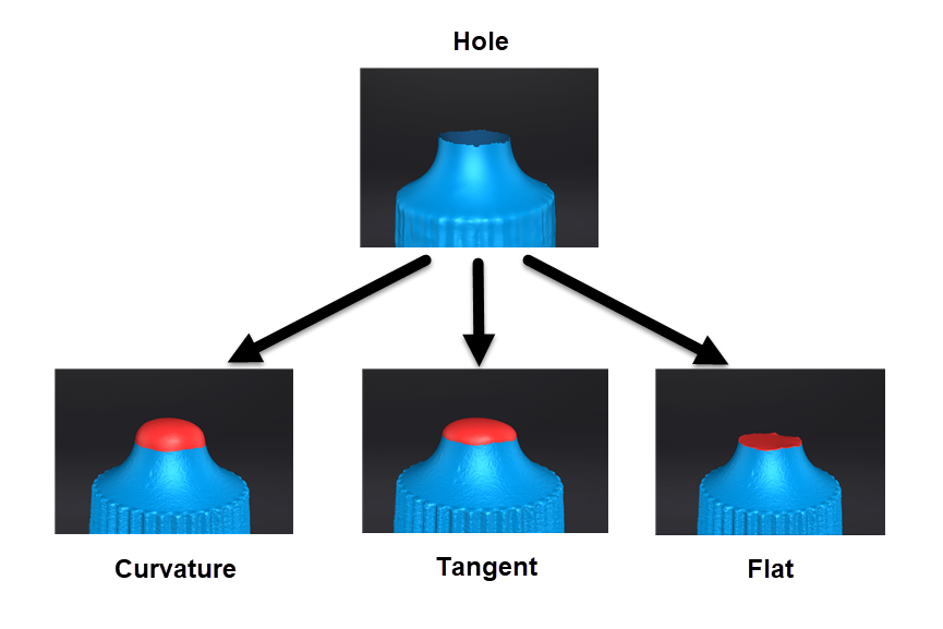 |
| Manual Hole Filling | After entering the manual hole filling mode, the hole edges are displayed green and get red after picking. The number of the holes and the number of holes filled will be displayed on the interface. | Select filling types before picking a hole and then click the edges to perform filling actions. Manually save the post-processing data. |
| Flip Normal | To redefine the front direction of the scanned data in reversal design. Hold Shift+left mouse button to select areas to be flipped. |
|
| Cutting Plane Tool | Define a plane to re-adjust the coordinate system of the scanned data. Hold Shift+left mouse button to select a plane by drawing a straight line and then activate Delete selection and close intersection or Delete selection. |
|
| Mirror | Take the front view plane of scan data as the working plane. Draw a straight line as the central axis and perform a symmetrical copy. Hold Shift+left mouse button to draw a straight line as the central axis and then click Keep the initial mesh. |
|
| Zoom | Adjust the scaling ratio of the model. Enter a value to set the ratio. The default is 100, indicating no zoom. |
|
Bottom Panel

| Icon | Function | Instruction |
|---|---|---|
 |
Select visible | To select data on the front view only. |
 |
Select through | To select data all through. |
Note
The other editing functions are the same as point cloud editing
Right Panel
| Icon | Function | Instruction |
|---|---|---|
 |
Open file | Open a file (STL, OBJ, PLY) for post processing. |
or  |
Export Your Scan | If the software version is V4.0.0.8 or above: If the software is in other version: Click to save the scanned data in the specified format. |
 |
Sketchfab Upload | Use your Sketchfab account to share the model. |
 |
Third-party software | Save the data and open with third-party software. |
| Shining3D Digital Cloud | Upload the model file to the cloud associated with the current account. Support data files in OBJ, STL, PLY format. |
|
| Texture Mapper | Merge HD texture images with the model file to enhance the overall texture quality of the scanned data. | |
| Model Display | After enabling the model display by clicking the icon or pressing F12, the model will rotate at a specified speed (Click  Note NoteThe model will only rotate and display from the current view after entering the model display interface. Exit and adjust the angles in the post-processing interface if other views are in need. |
Right Menu
| Instruction | |
|---|---|
| See in data editing and perform by using shortcuts. | |
| Display the data in the center according to the appropriate size. | |
| See in data editing. | |
| You can select different display types(triangles, wireframe, point cloud data as well as triangles and wireframes) and the data display mode of the 3D scene will change synchronously after switching.Note Only accessible after apply meshing. |
|
| The rotation center can be set on the data by the left mouse button, and click Esc to exit setting. | |
| After reset, the center of rotation is at the data center. |