Scanning Settings
After entering the Scan step interface, you can perform scan settings on the left side of the interface.
-
Camera Window
Preview the real-time image captured by the scanner camera. Previewing the effect through the camera window can assist in scanning data.
-
Brightness
Drag the slider to adjust the brightness for different material or color of the object to get better scanning data. Please ensure that the object is clearly visible within the camera window and that there is no excessive red color displayed on the object.
Col
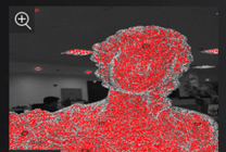
Brightness is too highCol
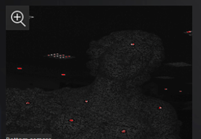
Brightness is too lowCol
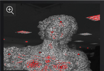
Brightness is normal
-
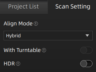
Align Mode
Support Hybrid (as default), Turntable Alignment, Turntable Coded Targets, Markers and Global Markers (you can open a global markers file or directly scan markers) modes.
Note
Under the Global Markers mode, please Scan Markers first and proceed with Global Optimization, and then switch to Scan Point Clouds. After scanning the point cloud, you can not switch to scanning global markers.
-
With Turntable (optional)
With this feature being enabled, the turntable can be used to help scanning.
- Please select Align Mode (Hybrid is not supported) first before choosing to use the turntable. After scanning a full circle, you can reselect the stitching mode.
- Number of rotations: Before scanning, you can set the number of rotations for the turntable (8 ~ 180), with a default value of 8.
- Use existed verify data (only supported in the Turntable Alignment mode): when enabled, the previous axis data will be used directly for alignment. If not enabled, recalibration is required before scanning and alignment. If there is no movement of the scanned object or turntable, you can enable this feature. However, if there is movement of the scanned object or turntable, please disable this feature and recalibrate the data.
-
HDR
With this feature being enabled, the scanning will be performed with a preset brightness level, and manual adjustment of the scanning brightness will not be possible. This mode is suitable for scanning objects that have a distinct contrast between black and white.
-
Camera Window
Preview the real-time image captured by the scanner camera. Previewing the effect through the camera window can assist in scanning data.
-
Brightness
Drag the slider to adjust the brightness for different material or color of the object to get better scanning data. Please ensure that the object is clearly visible within the camera window and that there is no excessive red color displayed on the object.
Col
Brightness is too highCol
Brightness is too lowCol
Brightness is normal
-
Plane Detection
With this feature being enabled, the software will automatically detect and erase the plane where the object is located. This helps reduce the chances of misaligning planes or objects with distinct features.
Note
- If you need to scan objects that are flat or have few features, it is recommended to paste markers for helping alignment.
- If the plane where the object is located can be scanned and affect the alignment effect, it is recommended to use the Auto Cutting Plane feature.
-
Data Quality Indicator
With this feature being enabled, the scanning data will be displayed in the form of quality chromatography.
- Green indicates high-quality scanning data at that location.
- Orange indicates low-quality scanning data at that location, indicating insufficient scanning. Further scanning is needed. Otherwise, insufficiently scanned data may disappear or display abnormally after data processing.
Note
By default, this feature is disabled for texture scanning, while it is enabled for other scanning modes.
-
Auto Cutting Plane
With this feature being enabled, during the scanning preview, the software will intelligently and in real-time identify the largest plane and mark it with a blue-green grid. The data below the marked plane will not be shown.
Note
- The unique plane marked during the scanning preview can change in real-time. The plane marked as the last one at the end of the scanning preview will be considered.
- This feature is disabled by default, and plane detection is enabled by default.
- If the Cutting Plane feature is used, this feature cannot be used.
-
Adjust Point Distance
To modify the point distance for the current single project, you can drag the slider or click the up/down arrow buttons: the default value is set to the point distance when creating a project group. The point distance range for both Handheld HD Scan and Handheld Rapid Scan is 0.2 mm to 3.0 mm.
Note
- If the number of projects in the current project group is greater than 1, this feature is not available.
- If the point distance is too small, it may result in insufficient memory for generating the mesh model or point cloud. It is recommended to modify the point distance based on the prompts in the pop-up window.