Settings
You can adjust the scanning settings for the current project in the scan interface.
Laser Scan
Align Mode
| Align Mode | Supported Marker Size | |
|---|---|---|
| Marker Alignment | Completes alignment using markers, suitable for objects with distinct geometric features, flat areas with minimal geometric features, and scenes requiring accuracy. | |
| Global Markers | Completes alignment using markers, suitable for objects lacking rich and variable geometric features and requiring high accuracy. | |
| Feature Alignment | Automatically completes alignment using the geometric features of the scanned object's surface, suitable for objects with rich geometric features or those that cannot have markers pasted. |
Note
Please make sure the remaining battery of the scanner is more than 25% when scanning with Feature Alignment.
Light Source Mode
| Light Source Mode | Description |
|---|---|
| 38 Lines | This mode is suitable for rapid scanning. |
| 7 Lines | This mode is suitable for detailed scanning. |
Object
It supports scanning of both normal objects and reflective objects. When scanning reflective objects, select Reflective to improve the scanning effect.
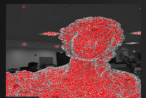
Brightness
The red dots in the camera view indicate overexposed areas. To improve scanning quality, it is recommended that you lower the camera brightness when there are large overexposed areas, or increase the camera brightness when the camera view is too dark.
Data Quality Indicator
When enabled, it will differentiate scan quality in colors: blue represents high-quality scanned data and yellow represents insufficient scanned data that requires further scanning.
Note
This function is unavailable when scanning global markers.
Outdoor Mode
To scan normally in the glare environment such as outdoors.
Caution
Please avoid direct sunlight when scanning objects.
Local Enlarged View
When the function is enabled, the scanning interface only displays the local perspective of the scanned object, which can be used for supplementary scanning of small holes.
View Lock
When the function is enabled, the view will be locked during scanning and not follow the scanning path, which can be used for scanning data from the locked view.
Resolution
You can adjust the point distance in real-time by dragging the slider or fill in the value before scanning and after pausing the scan.
Note
- If a project group contains more than one project, this function is not available for the second or later projects.
- It is recommended that you enable the data quality indicator and rescan the areas with lower quality (yellow areas) after changing the resolution.
IR Scan
-
Camera View
Preview the actual scene during scanning. Parameters can be adjusted accurately through the camera window.
-
Brightness
The red dots in the camera view indicate overexposed areas. To improve scanning quality, it is recommended that you lower down the camera brightness when there are large overexposed areas, or increase the camera brightness when the camera view is too dark.
Note
Click
 to enable auto exposure so the scanner can adjust the brightness automatically according to the actual situation.
Col
Brightness is too high
Col
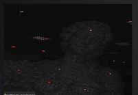
Brightness is too low
Col
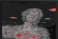
Brightness is proper
-
Scanning Distance
Drag the slider to adjust the scanning distance and the scanner scans only within the set distance. This function can effectively filter out unnecessary noise data.
-
Flat Detection
When enabled, it can reduce the possibility of misalignment.
Note
- If you need to scan flat or featureless objects, it is recommended that you place markers to assist with alignment.
- If this function does not work well, you can try using Remove Base.
-
Data Quality Indicator
When enabled, it will differentiate scan quality in colors: blue represents high-quality scanned data and yellow represents insufficient scanned data that requires further scanning.
Note
Show the color only before generating the point clouds.
-
Remove Base
When enabled, it will automatically identify the base plane and mask the scanned data below it during scanning; you can effectively filter out unnecessary noise data through this function, improving data processing efficiency.
Note
The marked plane during the scanning preview process can change in real-time and the last marked plane at the end of the scanning preview will be the final plane.
-
Resolution
You can adjust the point distance in real-time by dragging the slider or fill in the value before scanning and after pausing the scan.
Note
- If a project group contains more than one project, this function is not available for the second or later projects.
- It is recommended that you enable the data quality indicator and rescan the areas with lower quality (yellow areas) after changing the resolution.
-
Camera View
Preview the actual scene during scanning. Parameters can be adjusted accurately through the camera window.
-
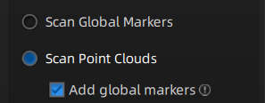
Scan Mode
Col
In Global Markers mode, scan the global markers first before scanning the point cloud.
Col
Note
- Click
 Open global markers file to import global markers files.
 - The Add global markers cannot be ticked during the scanning.
- If the Add global markers is ticked before scanning the point clouds, new markers recognized during the scanning process will be added, but the newly added markers will not be saved to the opened global markers file.
- Click
-
Brightness
The red dots in the camera view indicate overexposed areas. To improve scanning quality, it is recommended that you lower down the camera brightness when there are large overexposed areas, or increase the camera brightness when the camera view is too dark.
Note
Click
to enable the auto exposure and the scanner can adjust the brightness automatically according to the actual situation.
Col
Brightness is too high
Col
Brightness is too low
Col
Brightness is proper
-
Scanning Distance
Drag the slider to adjust the scanning distance and the scanner scans only within the set distance. This function can effectively filter out unnecessary noise data.
-
Flat Detection
When enabled, it can reduce the possibility of misalignment.
Note
- If you need to scan flat or featureless objects, it is recommended that you place markers to assist with alignment.
- If this function does not work well, you can try using Remove Base.
-
Data Quality Indicator
When enabled, it will differentiate scan quality in colors: blue represents high-quality scanned data and yellow represents insufficient scanned data that requires further scanning.
Note
Show the color only before generating the point clouds.
-
Remove Base
When enabled, it will automatically identify the base plane and mask the scanned data below it during scanning; you can effectively filter out unnecessary noise data through this function, improving data processing efficiency.
Note
The marked plane during the scanning preview process can change in real-time and the last marked plane at the end of the scanning preview will be final plane.
-
Resolution
You can adjust the point distance in real-time by dragging the slider or fill in the value before scanning and after pausing the scan.
Note
- If a project group contains more than one project, this function is not available for the second or later projects.
- It is recommended that you enable the data quality indicator and rescan the areas with lower quality (yellow areas) after changing the resolution.