Settings
Note
You can adjust scan settings on either the software or the device. Any changes made on one will synchronize with the other.
Laser Mode
![]()
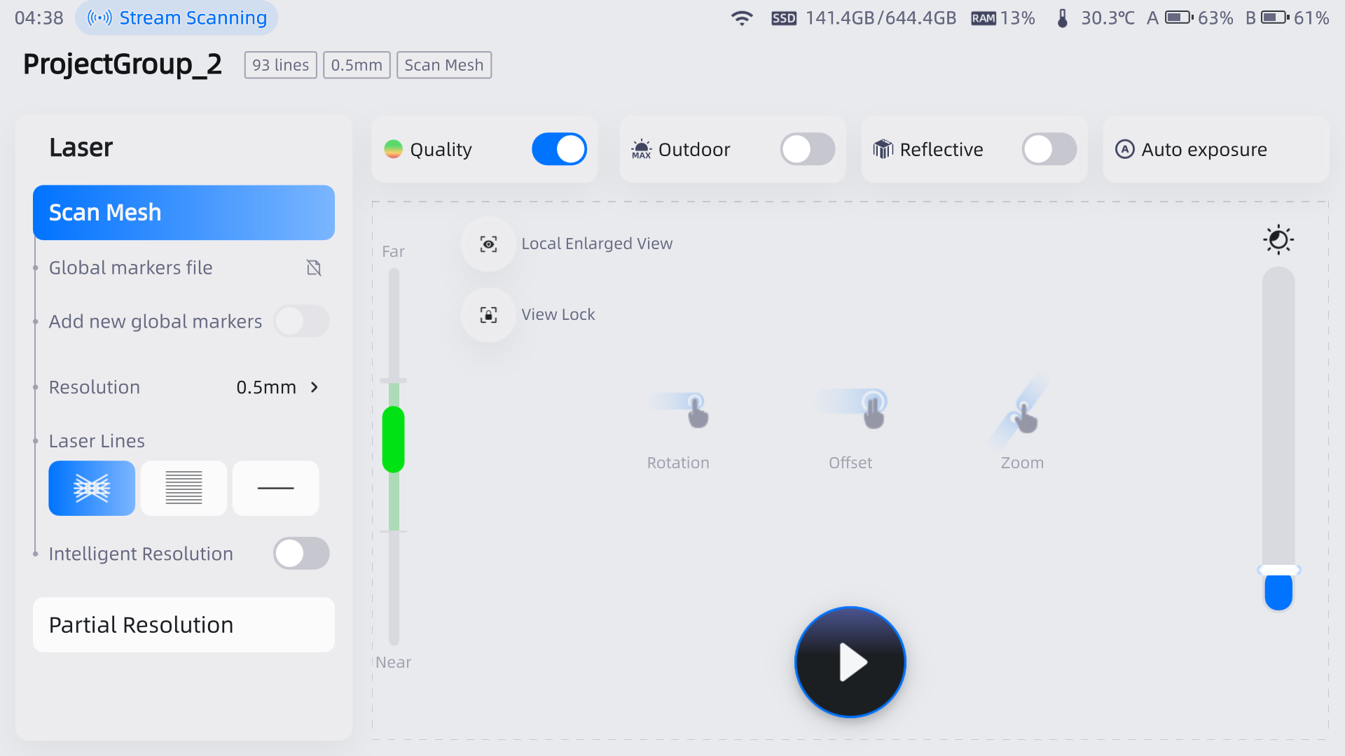
Scan Mode
Choose the proper scan mode to scan.
-
Scan Global Markers
This mode is used to scan markers on the surface of an object. You can quickly obtain the markers data of an object in this way and switch to Scan Mesh to continue scanning.
 Caution
- The scanner does not project laser lines during the scanning process.
- You can scan new markers after opening a global markers file.
- When switching to Scan Global Markers, the current scanned data will be cleaned up and the data can not be recovered.
-
Photogrammetry
This mode is generally suitable for high-precision industrial inspection. Depending on the size of the scanned object(s), you can import an appropriate scale bar file and use the scale bar(s) during scanning to improve the overall accuracy of the global markers data.
Note
For FreeScan Omni Lite, this function is an authorized feature. To unlock it, please contact our support team.
-
Scan Mesh
Directly scan to generate mesh data. This mode is suitable for most scanning scenarios.
 Note
NoteWhen the markers are not fully scanned in Scan Global Markers, you can check Add Global Markers to scan new global markers.
-
Partial Resolution
This mode is used for scanning when there is a high requirement for details in a specific area or when there are missing data in certain regions. By using this mode for targeted scanning, it can save scanning time and make the scanned data more accurate and complete.
Point Distance
Note
When there is only one project within the project group, you can adjust the point distance in real-time in the scan mesh mode.
Laser Mode
| Scan Mode | Point Distance |
|---|---|
| Scan Mesh | 0.05 mm ~ 10.0 mm |
| Partial Resolution | Standard: 0.05 mm ~ 5.0 mm High: 0.05 mm ~ 2.5 mm |
Note
- Standard: Half of the point distance in scan mesh mode; high: One quarter of the point distance.
- If the resulting distance is less than the minimum allowed distance of 0.05 mm, the partial resolution mode is not available.
IR Mode
| Scan Mode | Point Distance |
|---|---|
| Scan Point Cloud | 0.1 mm (small objects) ~ 3.0 mm |
Marker Size
| Scan Mode | Marker Sizes (mm) |
|---|---|
| Global Markers | 3, 6, 12 |
| Photogrammetry | 6, 12 |
| Mesh | 3, 6, 12 |
Light Source Mode
According to the scanning requirements, you can choose different light source modes.
| Light Source Mode | |
|---|---|
| 93 Lines | This mode can be used to scan large objects. |
| 25 Lines | This mode can be used to scan fine details. |
| 1 Line | This mode can be used to scan deep holes and pocket area. |
Object
It supports scanning of both normal objects and reflective objects. When scanning reflective objects, select Reflective to improve the scanning effect.
Brightness
For objects of different materials and colors, adjust the brightness of the scanner to can better.
Col
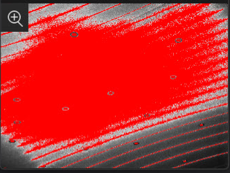 Too Bright
Col
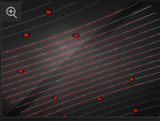 Proper
Col
 Too Dark
Outdoor Mode
To scan normally in the glare environment such as outdoors.
Caution
Please avoid direct sunlight when scanning objects.
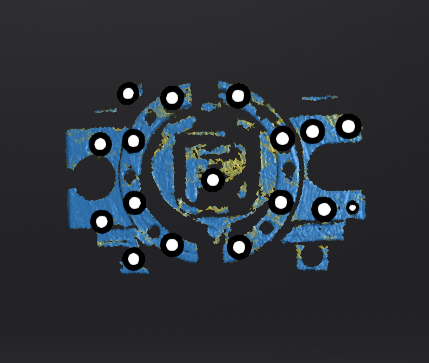
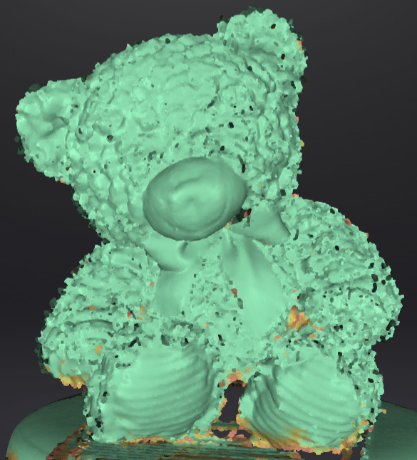
Data Quality Indicator
Differentiating scan quality in colors: blue represents high-quality scanned data and yellow represents insufficient scanned data that requires further scanning. Insufficiently scanned data may disappear or become anomalous after editing.
Note
This function is not available for scanning in scan markers mode or photogrammetry mode.
Scan in Point Cloud
After enabling the Scan in Point Cloud, the point cloud data will be displayed during the scanning process, thereby reducing GPU memory consumption.
Note
- Mesh data will be displayed after pausing the scanning whether this mode is enabled or not.
- You can switch another scan mode when only global markers data is present or after all data is cleared.
- Scan modes cannot be switched during pre-scanning, the scanning process, or when data present in the scene.
- Projects within the same project group can adopt different states: Project A within the group can have this mode enabled, while Project B can have it disabled.
- This function is only supported by Scan Mesh mode and Partial Resolution mode.
Local Enlarged View
When the function is enabled, the scanning interface only displays the local perspective of the scanned object, which can be used for supplementary scanning of small holes.
View Lock
When the function is enabled, the view will be locked during scanning and not follow the scanning path, which can be used for scanning the data of the locked view.
Deep Hole Optimization
When scanning deep holes, please enable it to enhance the scanning depth and the integrity of the scanned data.
Caution
-
Enabling this function may also result in an increase in noise.
-
This mode can only be enabled when the light source mode is selected as 1 line.
Intelligent Resolution
After enabling Intelligent Resolution, the software automatically adjusts the mesh resolution based on the curvature of the scanned object. Multiple scans are required during the scanning process to achieve high-quality data and make the features of the scanned object more clear. After selecting High Intelligent Resolution or Standard Intelligent Resolution and generating mesh, click Preview in the Mesh Optimization interface to view the intelligent resolution effect: areas with high curvature will have higher data density.
Note
- Enabling High Intelligent Resolution requires a point distance in the project greater than 0.4 mm.
- Enabling Standard Intelligent Resolution requires a point distance in the project greater than 0.2 mm.
- Only project files with the same intelligent resolution can exist in a project group; if a project with a different resolution is imported into the current project group, the resolution of the imported project will be changed to the resolution consistent with the project in the current project group.
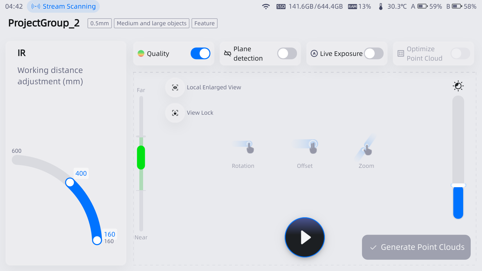
IR Mode
![]()
Scan Mode
-
Scan Point Cloud (IR Mode)
Directly scanning point clouds. After the scanning is complete, point cloud data needs to be generated.
Working Distance Adjustment
The effective area of the scanned data. It can be adjusted according to the size of the object and the alignment mode. The larger the value, the easier it is to scan data with far distance, but some data details will be lost.
| Scan Mode | Minimum Scanning Distance | Maximum Scanning Distance | Scanning Distance Range |
|---|---|---|---|
| Portrait | 160 mm | 1400 mm | ≥ 200 mm |
| Object | 160 mm | 600 mm 250 mm (small objects) |
≥ 200 mm ≥ 40 mm (small objects) |
Data Quality Indicator
Blue represents high-quality scanned data and yellow represents insufficient scanned data that requires further scanning. Insufficiently scanned data may disappear or become anomalous after editing. For more, see Data Quality Indicator.
Hair Mode
When the function is enabled, it is easier to capture hair but the data noise will increase.
Note
Only available in portrait scan mode.
Col
 Turn off
Col
 Turn on
Plane Detection
When enabled, it can reduce the possibility of misalignment.
Note
- This function is only available in Feature or Hybrid align mode.
- This function cannot be used for scanning objects with few features or flat surfaces; when scanning such objects, the software will prompt "Please scan non-planar areas."
Local Enlarged View
When the function is enabled, the scanning interface only displays the local perspective of the scanned object, which can be used for supplementary scanning of small holes. For more, see Local Enlarged View in Laser Mode.
View Lock
When the function is enabled, the view will be locked during scanning and not follow the scanning path, which can be used for scanning the data of the locked view. For more, see View Lock in Laser Mode.