Calibration
Follow the steps provided by the calibration wizard on the right side of the interface.
Caution
Please contact technical support if the message (Wrong laser calibration file) prompts.
Quick Calibration
Steps
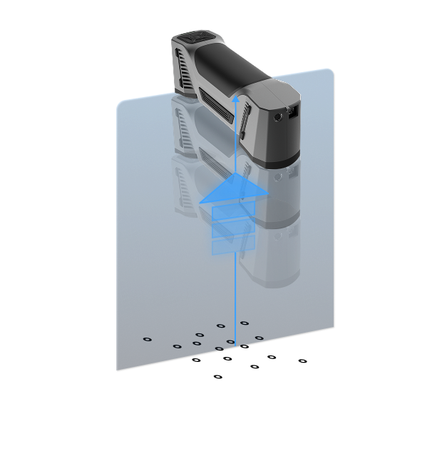
- Place the calibration board horizontally.
- Place the scanner in the same direction as shown in the figure.
- Align the center point of the device with the center point of the gray circle on the calibration board.
-
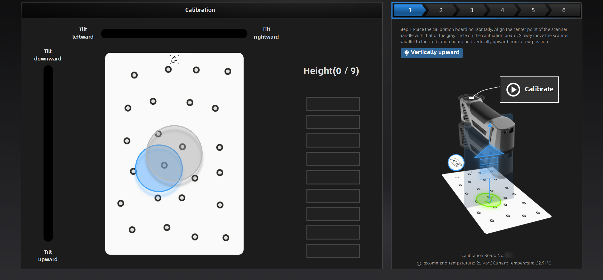
Press the start button on the scanner or click Calibrate on the interface to start calibration.
-
Move the device slowly and adjust the distance between the scanner and the calibration board according to the height indicating box.
- Keep moving until all height boxes turn green.
- Adjust the scanner position according to the prompts on the software interface. Repeat steps 4 to 5 to complete the calibration for the remaining directions.
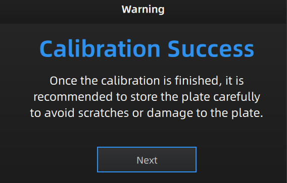
- Check the calibration result.
Note
- Please calibrate again if the calibration fails.
- During the calibration process, please ensure that there are not a large number of markers around the calibration board, so as not to affect the calibration accuracy.
- Please contact the supplier or technical support if the calibration still fails after several attempts.
Col
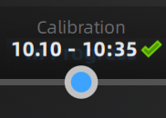
The navigation bar at the top of the interface will display the calibration time when the calibration is completed successfully. If no further calibration is performed within 7 days after the completion of the previous calibration, ![]() will appear. Please perform calibration again to ensure scanning accuracy.
will appear. Please perform calibration again to ensure scanning accuracy.
Col
Laser Plane Calibration
It is recommended to perform laser plane calibration when the device exhibits excessive noise or scanning failures during the scanning process.
Note
Before use, enable Laser Plane Calibration in Settings > Laser Scan Settings.

-
Please attach markers before calibration:
- A non-reflective solid light-colored plane
- Within a range of 600 mm × 800 mm
- Attach at least 16 markers, each 6 mm in size.
- Outer marker spacing: 200 - 300 mm
- Inner marker spacing: 100 - 150 mm
Caution
Do not attach markers to surfaces with features or uneven surfaces.
-
Align the attached markers, position the device according to the direction shown in the diagram, with the center point corresponding to the attached markers. Adjust the height to fill the height bar in the software interface to green.