Connection
Please connect all parts as the following steps.
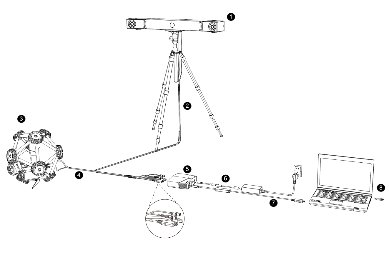
Introduction to the Parts
| No. | Name | |
|---|---|---|
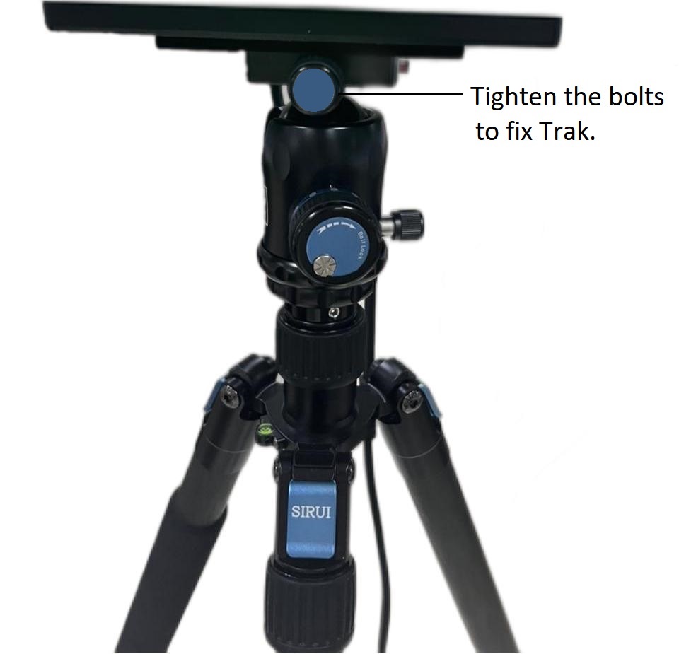
| 1 | Optical Tracker | To be installed on a tripod. |
| 2 | Tracker Cable | |
| 3 | Laser Scanner | |
| 4 | Scanner Cable | |
| 5 | Hub | To connect the tracker, the scanner and the computer. |
| 6 | Hub Power Cable | To connect the hub to the power supply. |
| 7 | Data Cable | To connect the hub with the computer. |
| 8 | Dongle | To authorize the use of the software. |
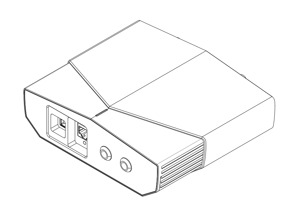
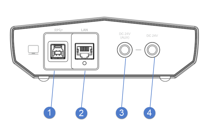
Introduction to the Hub
| No. | Name | |
|---|---|---|
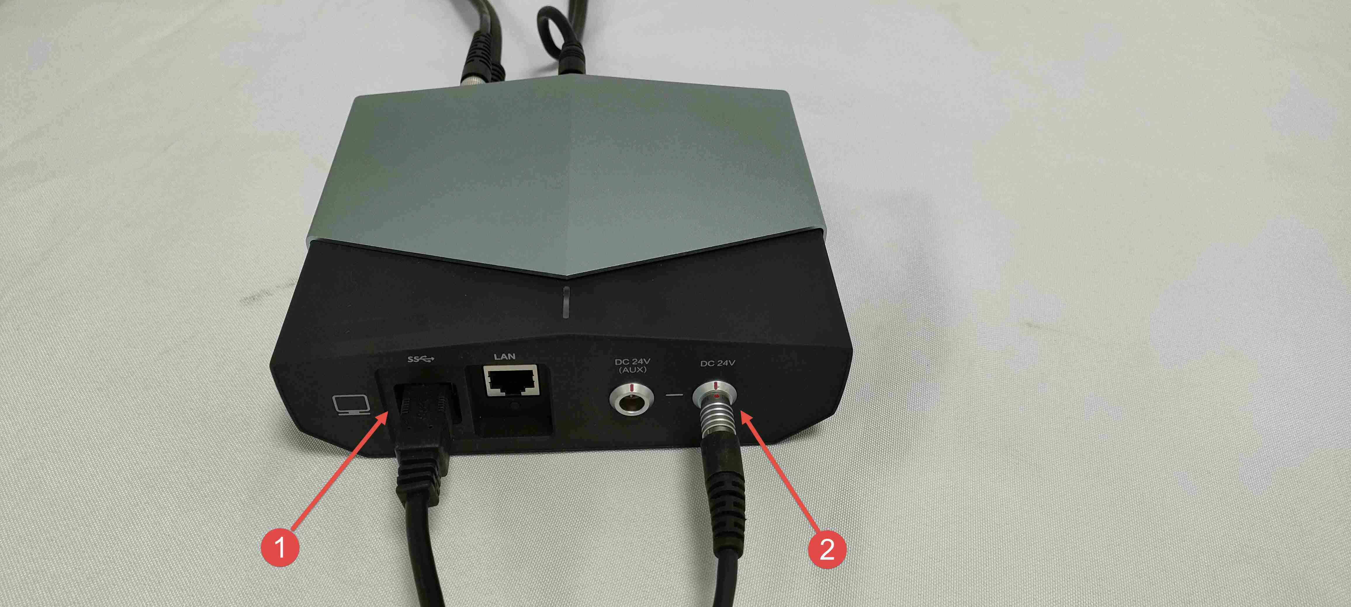
| 1 | USB Port | To connect the tracker, the scanner and the computer to transmit data. |
| 2 | Network Port | To connect the computer or the switch to test |
| 3 | Auxillary Power Input | To connect the power adapter (24 V, 3.75 A). It is only available when an extended tracker is used. |
| 4 | System Power Input | To connect the power adapter (24 V, 3.75 A). It is a main power input of the system |
| No. | Name | |
|---|---|---|
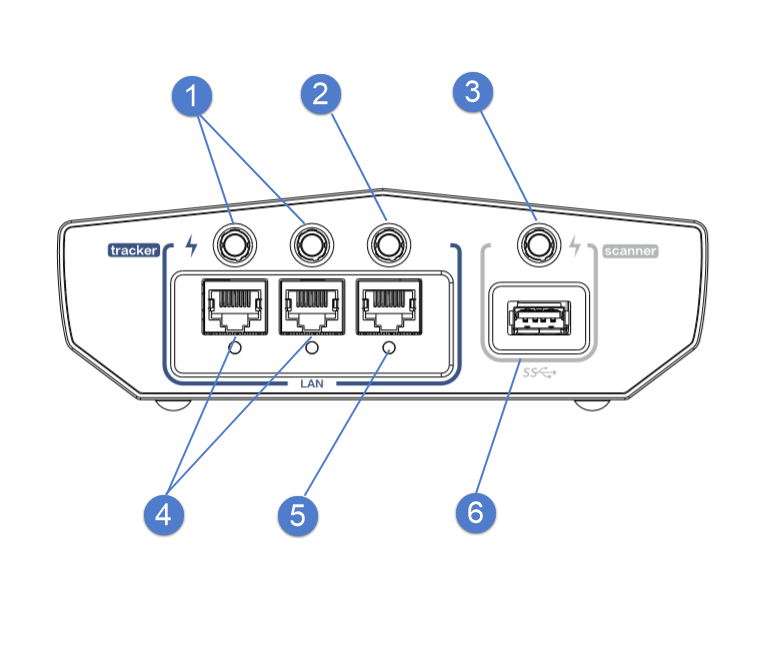
| 1 | Power Output | To power on the extended tracker |
| 2 | Power Output | To power on the tracker |
| 3 | Power Output | To power on the scanner |
| 4 | Network Port | To transmit data of the extended tracker |
| 5 | Network Port | To transmit data of the tracker |
| 6 | USB Port | To transmit data of the scanner |
Connection
-
Install the tracker on the tripod and tighten the bolts.
-
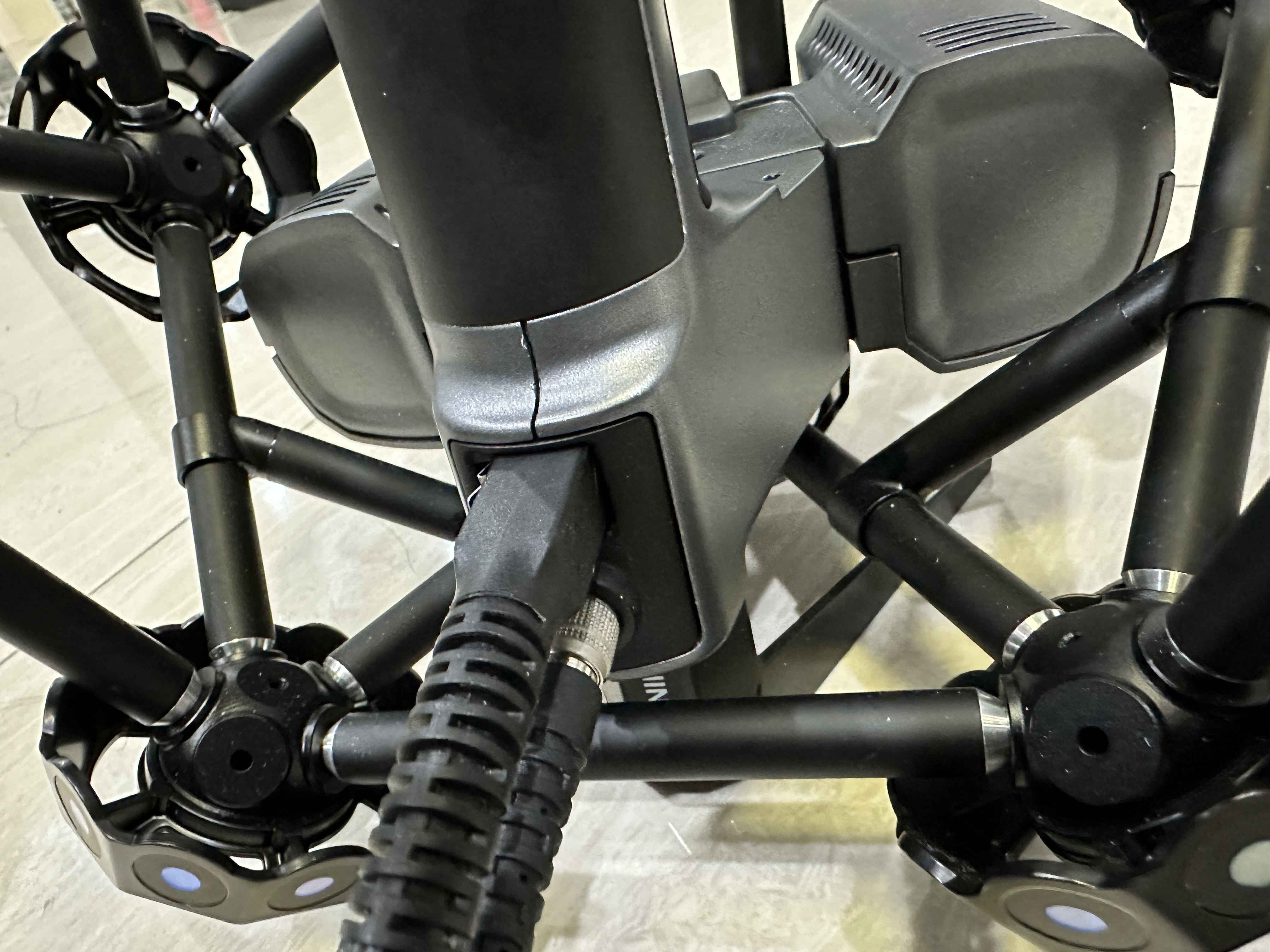
Connect one end of the tracker cable with the tracker.
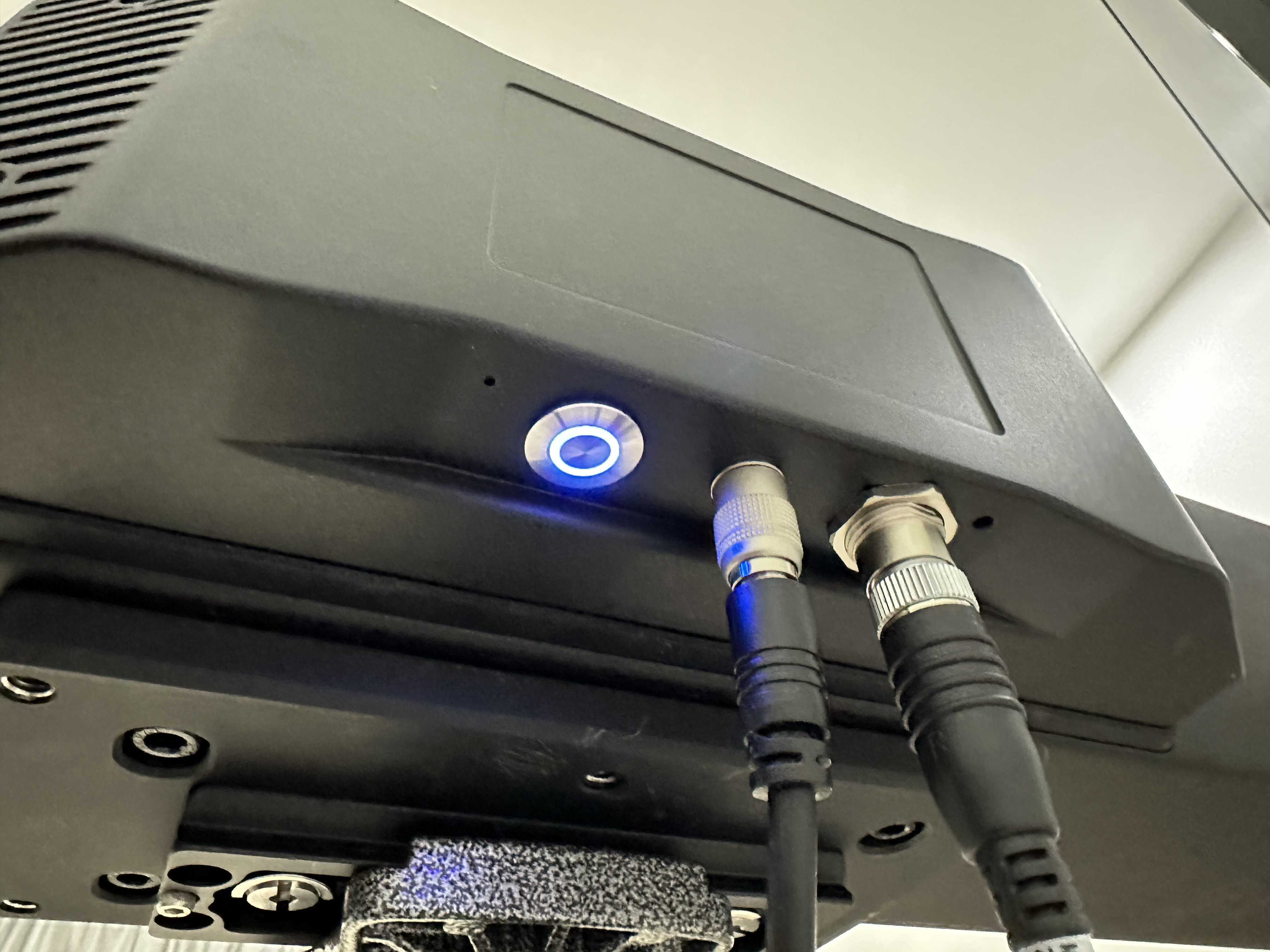
-
Connect the other end of the tracker cable with the hub.
-
Connect one end of the scanner cable with the scanner.
-
Connect the other end of the scanner cable with the hub.

-
Connect the hub and the power supply with the hub power cable.
-
Connect the hub and the computer with the data cable.
-
Power on the device.
Warning
Please do not access too many hubs in the same USB port, otherwise it will affect the normal operation of the software.