Settings
You can adjust scan settings during pre-scanning or scanning, including the mode, light source, object, brightness and so on, to achieve an ideal result.

Scan Mode
You can select Scan Mesh, Partial HD Scanning or Scan Global Markers / Photogrammetry to scan.
Note
When the scanner is in Scan Mesh and there is only one project within the project group, you can adjust the point distance in real time.
High-Speed Mode
You can improve the scanning speed when it is enabled.
Light Source Mode
| FreeScan TE25W | Description |
|---|---|
| 50 Lines | 50 crossed lines are ready to scan a large object. |
| 7 Lines | 7 parallel lines are ready to scan fine details. |
| 1 Line | A single laser line is ready to scan deep holes and pocket area. |
Object
Select the mode according to the material of the object you are ready to scan.
Brightness
Drag the slider and adjust the brightness until the scanned data or the markers are clearly visible and complete. Too high brightness may result in much noises in the scanned data.
Data Quality Indicator
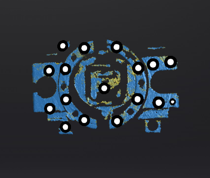
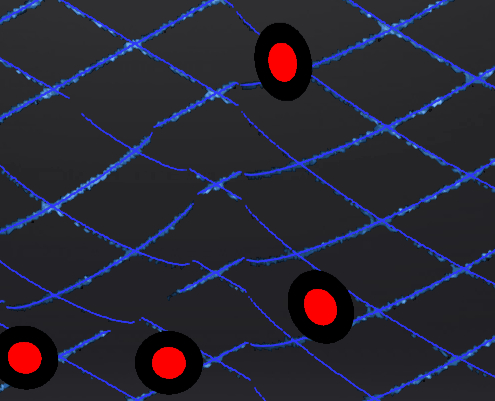
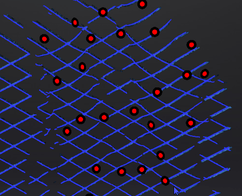
Quality of the scanned data can be displayed by different colors: blue represents a high quality and yellow represents an insufficient scanned data, which needs further scanning. Insufficiently scanned data may disappear or become anomalous after editing.
Note
This function is not available for scanning in scan markers mode.
Local Enlarged View
When the function is enabled, the scanning interface will display a local perspective of the scanned object, which can be used for supplementary scanning of small holes. It is recommended to enable the function under 0.2 mm point distance.
View Lock
The view in the scanning interface will not vary with the movement of the scanner when the function is enabled.
Field of View
When the scanner is outside the view field of the tracker, the scanner may not be able to scan data or the quality of the scanned data may be poor. In such a situation, you can enable this function. Once enabled, the view field of the tracker will be visualized in the 3D scene, allowing you to see the relative positions of the tracker, scanner, and the object being scanned.
During scanning, you can use this function to adjust the position of the tracker to ensure that the object being scanned and the scanner are within the view field of the tracker.
Caution
If you move the tracker in a real-world scene, the model position of the tracker in the 3D scene will not change, but the relative position of the scanned object in the 3D scene will change in real-time.
Intelligent Resolution
After enabling Intelligent Resolution, the software automatically adjusts the mesh resolution based on the curvature of the scanned object. Multiple scans are required during the scanning process to achieve high-quality data and make the features of the scanned object more clear. After selecting High Intelligent Resolution / Standard Intelligent Resolution and generating mesh, click Apply in the Mesh Processing interface to view the intelligent resolution effect: areas with high curvature will have higher data density.
Note
- Enabling High Intelligent Resolution requires a point distance in the project greater than 0.4 mm.
- Enabling Standard Intelligent Resolution requires a point distance in the project greater than 0.2 mm.
- Intelligent resolution is only available for Scan Mesh in the Trak Mode and the Laser Mode.
- Intelligent resolution only applies to individual project files. Different project files within a project group can have different intelligent resolutions.