Interface
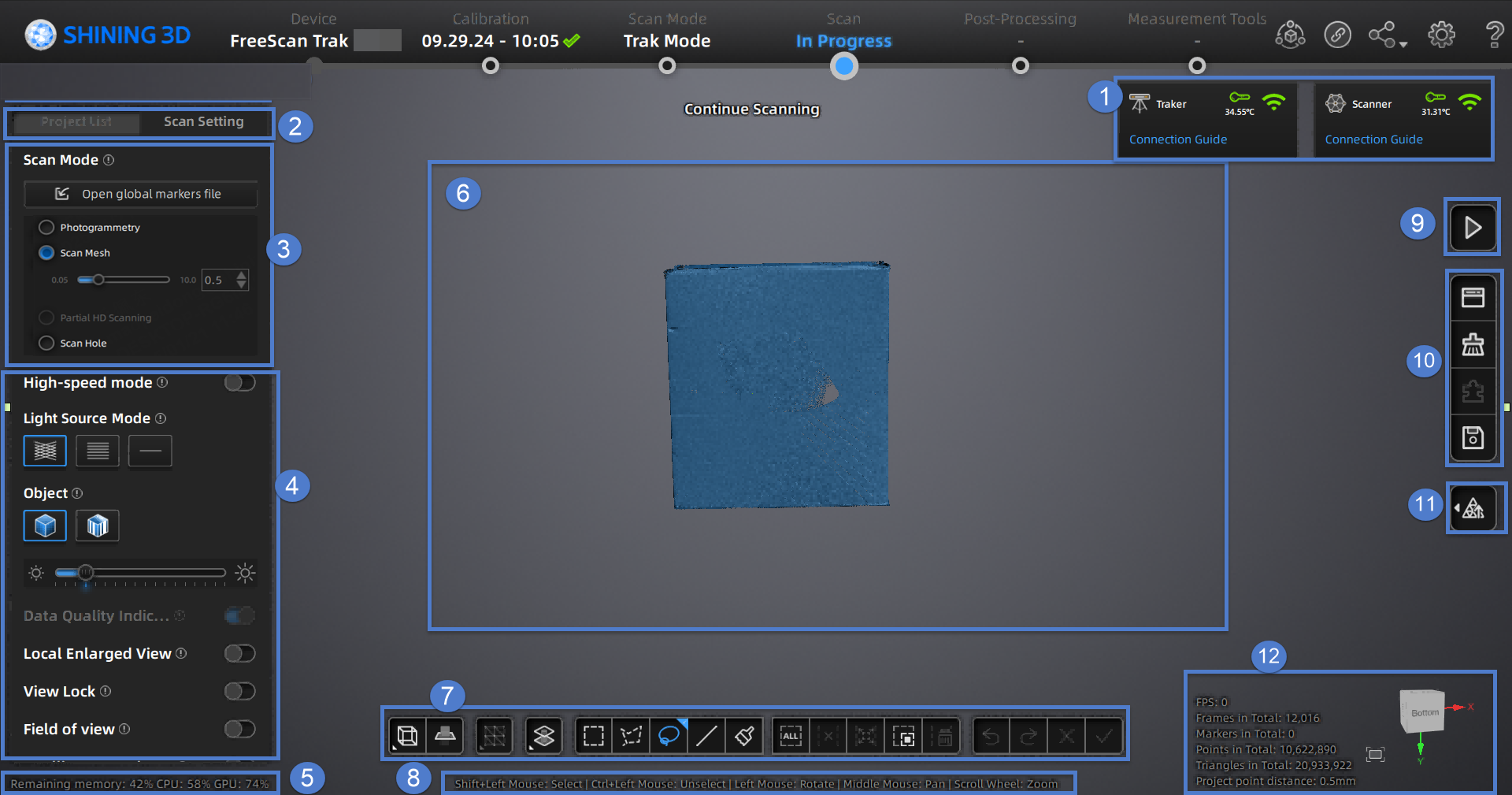
Function Preview
Note
The screenshot shown above is for illustrative purposes only. Always refer to the actual software interface.
① Connection Information
When the device is connected successfully, click ![]() to view the relevant information about the device connection.
to view the relevant information about the device connection.
② Project Group and Scan Setting
To manage your project group and set scanning parameters.
③ Scan Mode
You can choose Trak Mode or Laser Mode for scanning based on the application scenario.
To switch among Scan Mesh, Partial HD Scanning,Scan Global Markers / Photogrammetry and Scan Hole.
Note
Photogrammetry is only supported when selecting Trak Mode (real-time scanning).
④ Parameter Settings
See more details in Parameter Settings.
⑤ Remaining Memory, CPU Usage and GPU Usage
- Remaining Memory: To display the percentage of remaining memory.
- CPU Usage: To display the CPU Usage of the computer in real time. You may need to close other unrelated software if it is too high.
- GPU Usage: To display the GPU Usage of the computer in real time.
⑥ Preview / Scanning Window
To preview the model and check the scanned model.
⑦ Data Editing
To edit data after scanning. See more details in Data Editing.
⑧ Keyboard Shortcuts
To change the perspectives and move the model by the composition of keys.
⑨ Buttons
Click ![]() to preview the scanning; click
to preview the scanning; click ![]() to start scanning; click
to start scanning; click ![]() to pause scanning.
to pause scanning.
⑩ Function
To import the project file and to align, delete and save the model data.
⑪ Mesh
See more details in Mesh Processing.
⑫ Others
Display FPS, frame amount, point amount of the project and other information.
| Function | |
|---|---|
Fit View |
Click |
View controller |