Connection
Please connect all parts as the following steps.
Introduction to the Parts
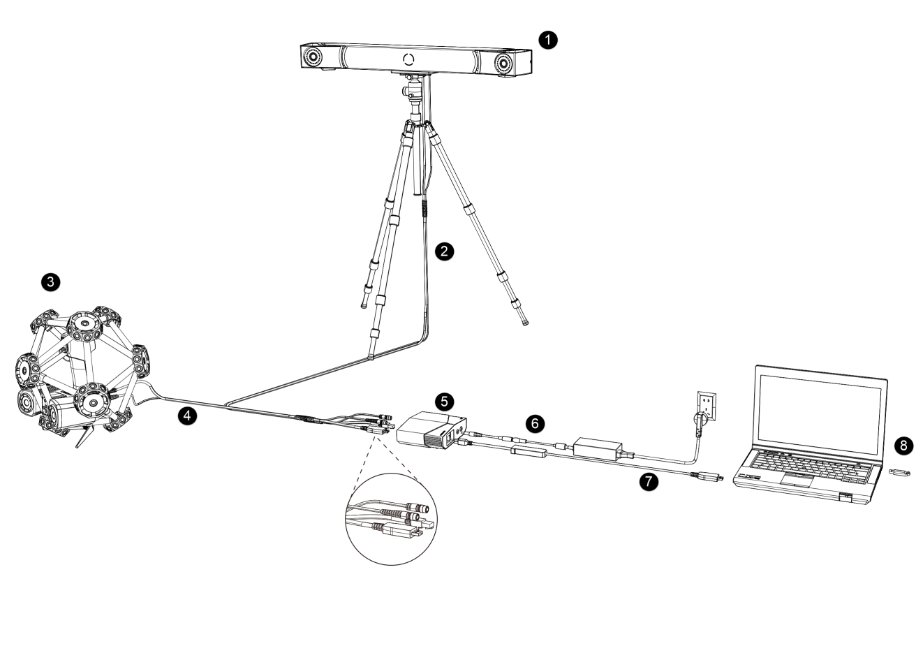
| No. | Name | |
|---|---|---|
| ① | Optical Tracker | An optical tracker, which can be installed on a tripod. |
| ② | Tracker Cable | |
| ③ | Laser Scanner | Device for contactless detection of surfaces. |
| ④ | Scanner Cable | |
| ⑤ | Hub | To connect the tracker, the scanner and the computer. |
| ⑥ | Hub Power Cable | To connect the hub to the power supply. |
| ⑦ | Data Cable | To connect the hub with the computer. |
| ⑧ | Dongle | To authorize the use of the software. |
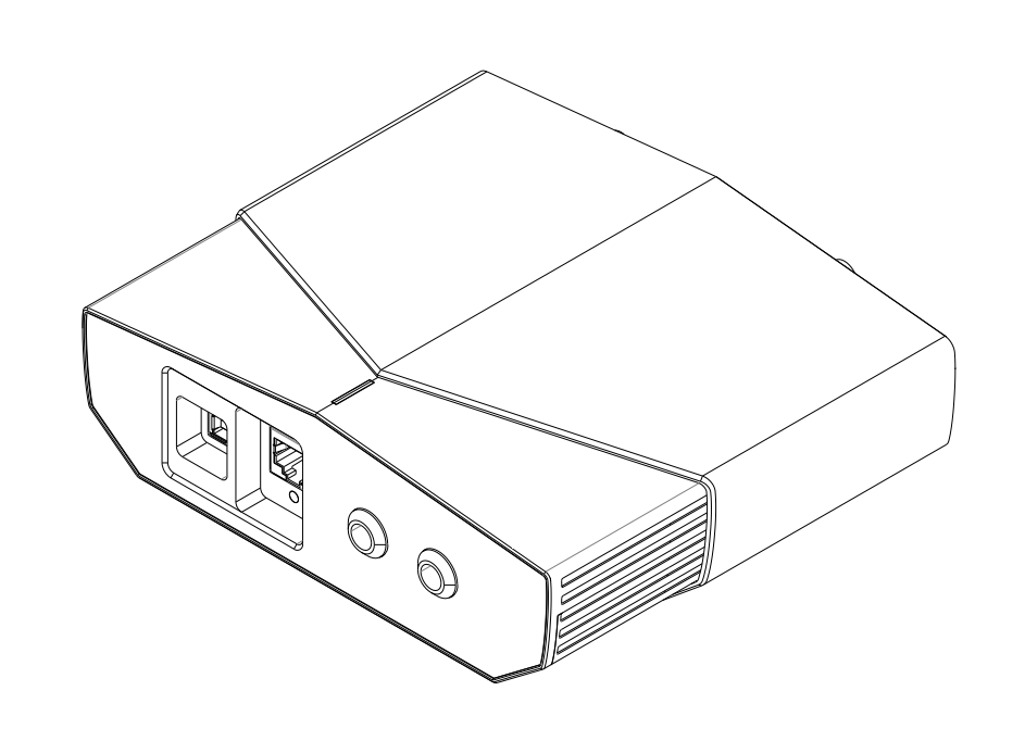
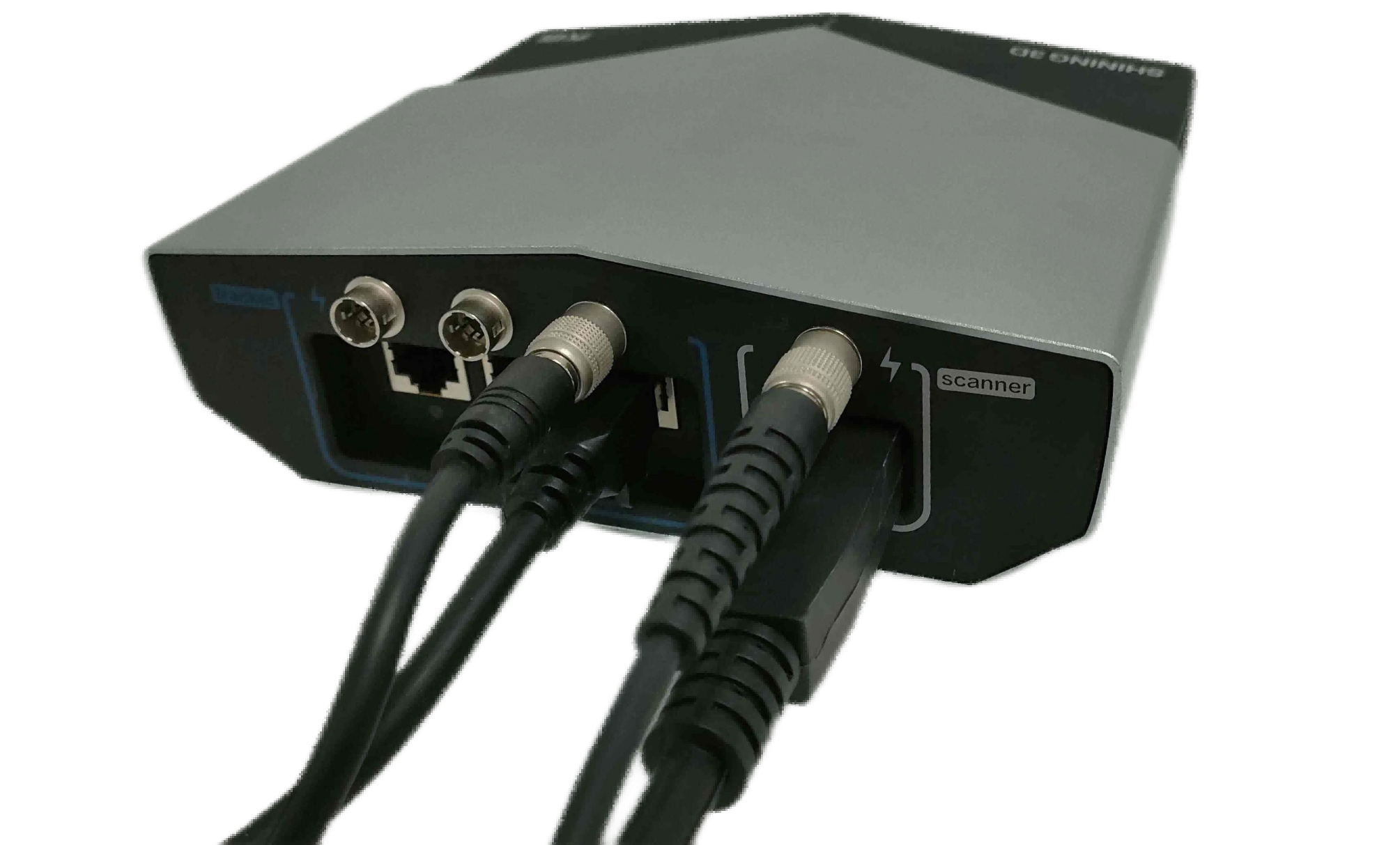
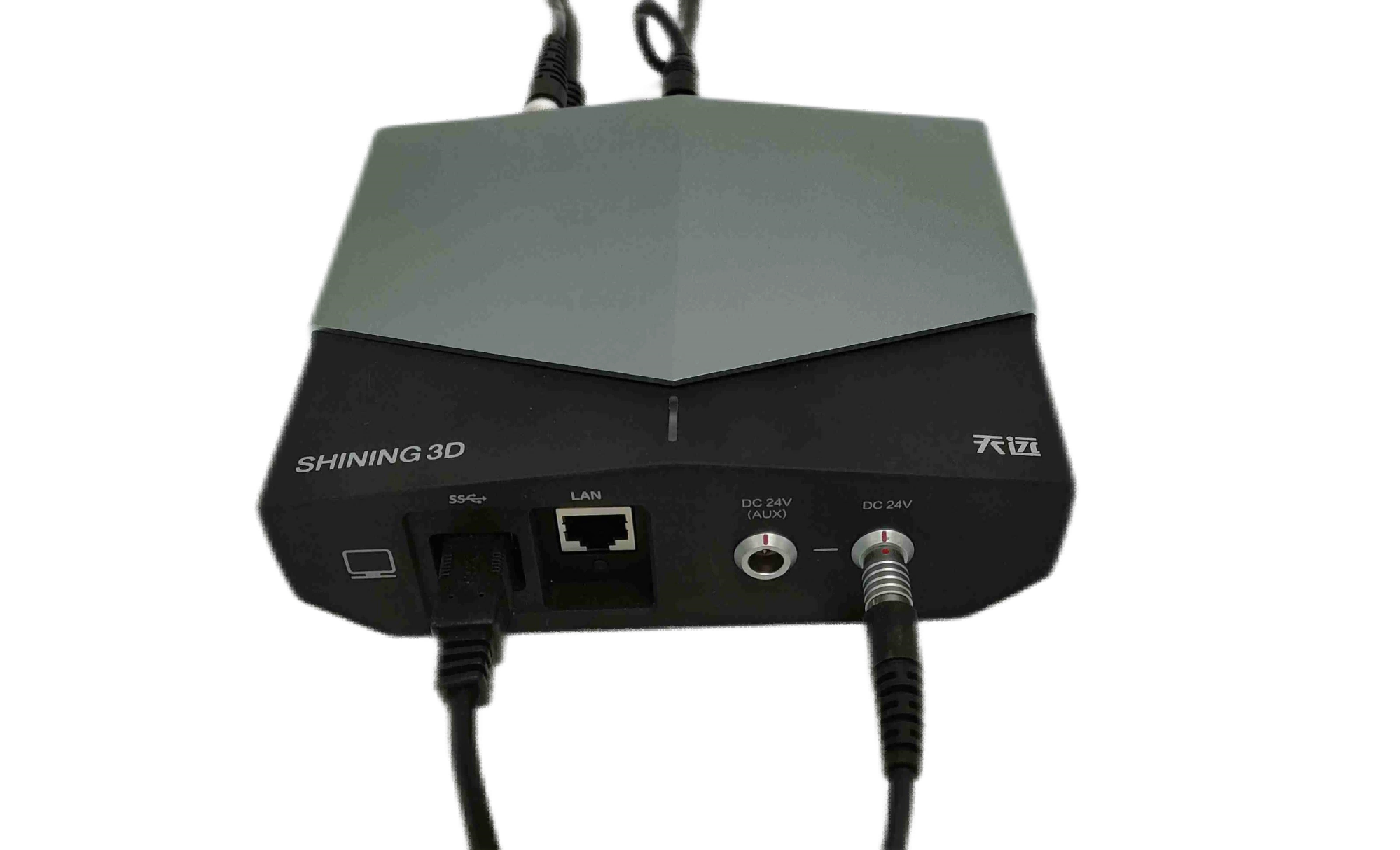
Introduction to the Hub
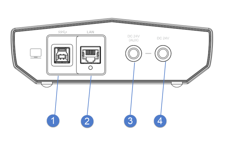
| No. | Name | |
|---|---|---|
| ① | USB Port | To connect the tracker, the scanner and the computer to transmit data. |
| ② | Network Port | To connect the computer or the switch to test. |
| ③ | Auxillary Power Input | To connect the power adapter (24 V, 3.75 A). It is only available when an extended tracker is used. |
| ④ | System Power Input | To connect the power adapter (24 V, 3.75 A). It is a main power input of the system. |
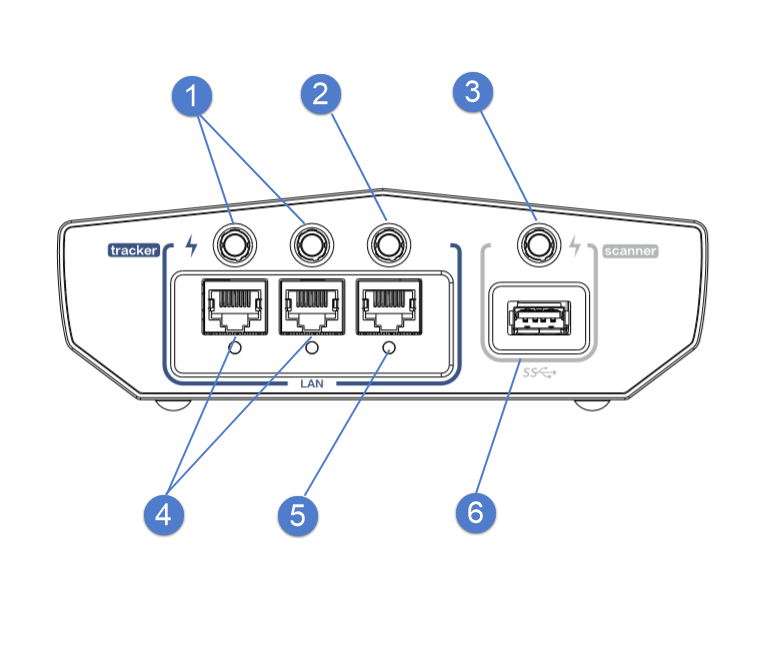
| No. | Name | |
|---|---|---|
| ① | Power Output | To power on the extended tracker. |
| ② | Power Output | To power on the tracker. |
| ③ | Power Output | To power on the scanner. |
| ④ | Network Port | To transmit data of the extended tracker. |
| ⑤ | Network Port | To transmit data of the tracker. |
| ⑥ | USB Port | To transmit data of the scanner. |
Wired Connection
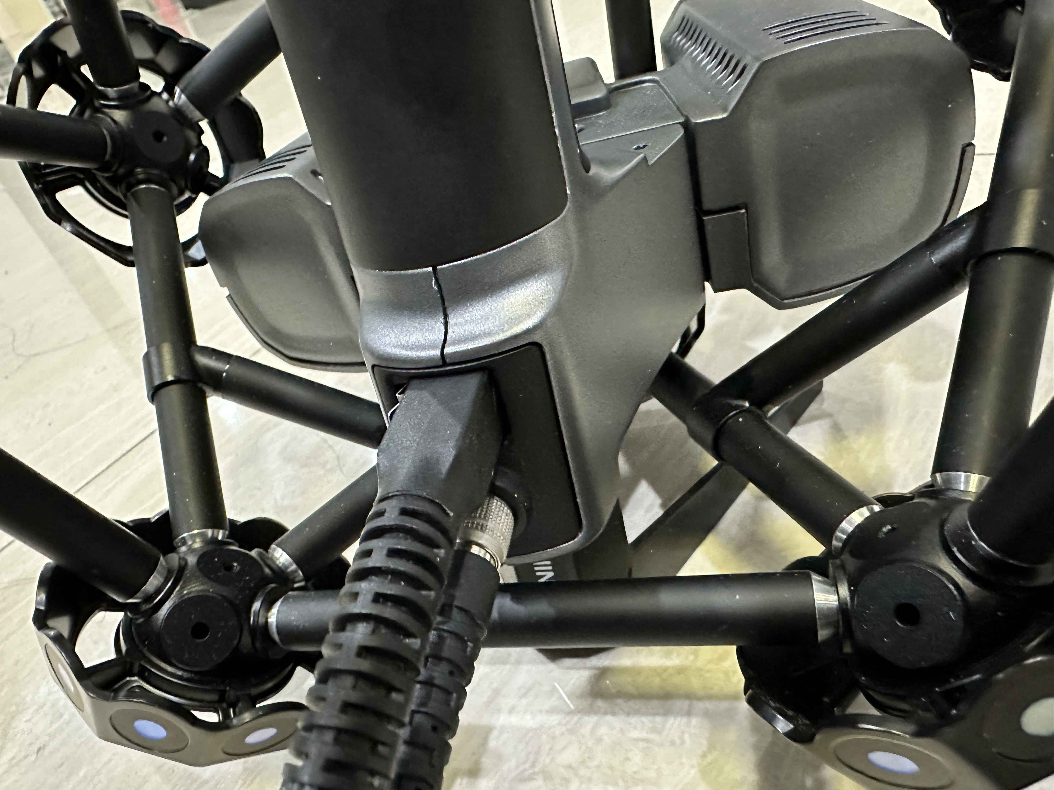
- Install the tracker on the tripod and tighten the bolts.
-
Connect one end of the tracker cable with the tracker.
-
Connect the other end of the tracker cable with the hub.
-
Connect one end of the scanner cable with the scanner.
-
Connect the other end of the scanner cable with the hub.
-
Connect the hub and the outlet with the hub power cable.
-
Connect the hub and the computer with the data cable.
-
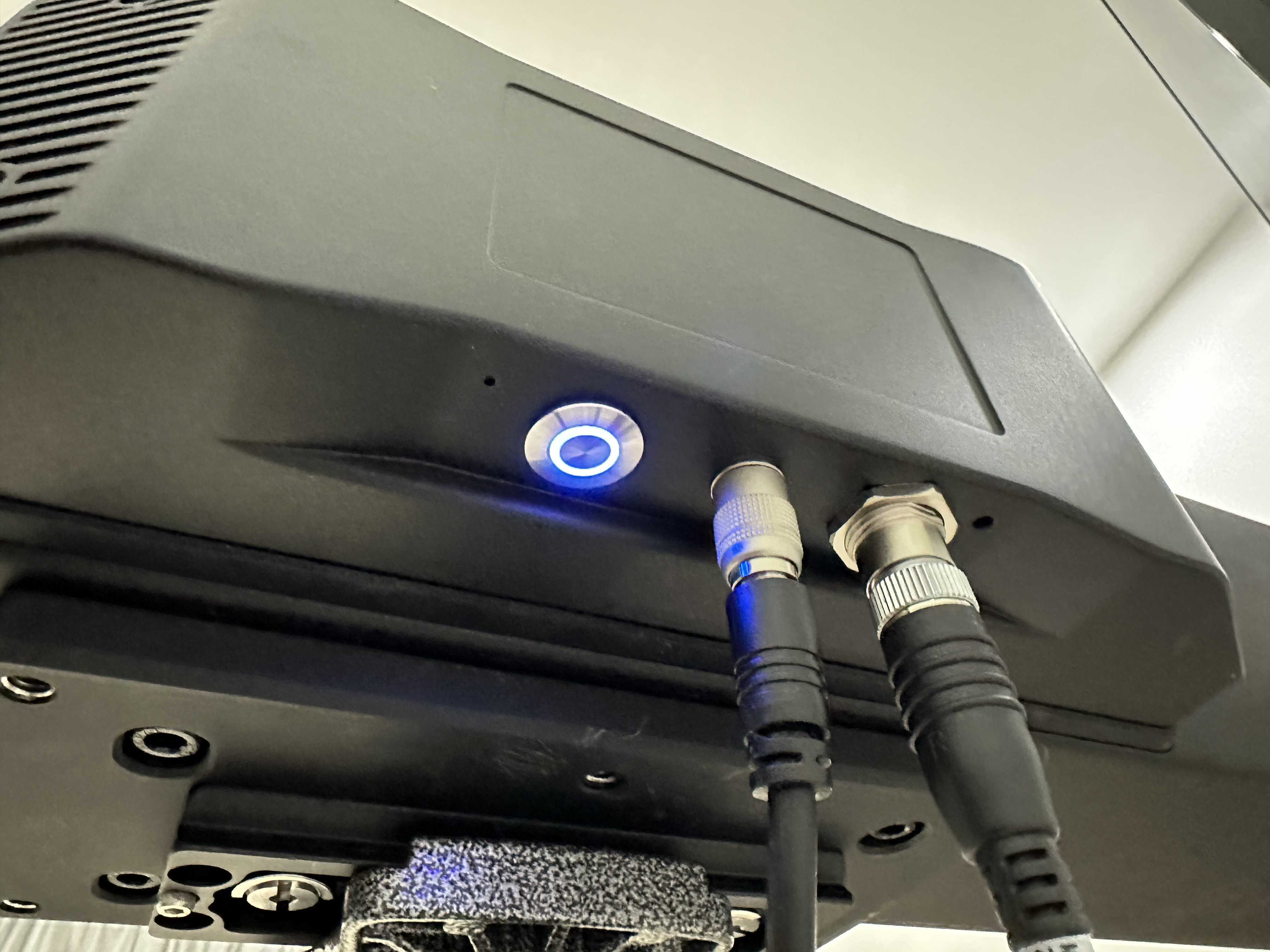
Power on the device.