Settings
You can adjust scan settings during pre-scanning or scanning, including the mode, light source, object, brightness and so on, to achieve an ideal result.
Scan Mode
You can scan in Scan Mesh or Photogrammetry.
Working Space
You can choose from three different working spaces: Near, Standard, and Far.
Note
- If there are multiple projects within one project group, all projects can only select the same working space.
- You can switch the type of the working space and modify the point distance during scanning; the point distance after meshing will be the final point distance.
| Working Space | Normal Point Distance | Point Distance to Enable the Intelligent Resolution | Recognized Marker Size | |
|---|---|---|---|---|
| Near 300-800 mm |
≥ 0.4 mm | > 0.8 mm | 6 mm | |
| Standard 600-1500 mm |
≥ 0.4 mm | > 0.8 mm | 6 mm; 12 mm |
Suitable for projects with small point distances and high detail requirements. |
| Far 1200-2600 mm |
≥ 3 mm | > 6 mm | 12 mm |
Marker Size
Two sizes of markers can be selected: 6 mm and 12 mm in diameter (default is all selected). You can check the marker size based on your scanning needs; once checked, only the markers with matched sizes will be recognized during scanning.
Note
- Please select at least one marker size.
- The marker size cannot be changed during preview, scanning, pause, and editing states.
Object
Select the mode according to the material of the object you are ready to scan.
Brightness
Scanning brightness refers to the intensity of light that is projected onto the object being scanned when using the device. If the brightness is too high or too low, it can affect the quality and integrity of the scanning data. Therefore, it is recommended that you adjust the brightness by dragging the slider before or during the scanning process to ensure optimal scanning results.
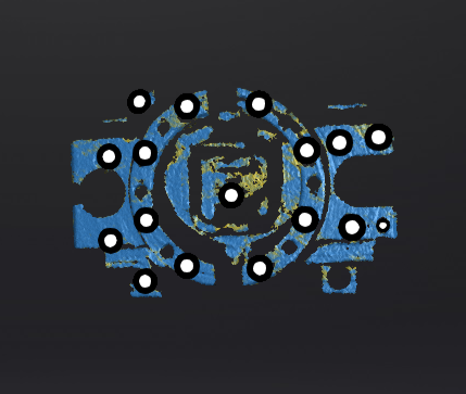
Data Quality Indicator
The quality of the scanned data is shown by a color indicator. Blue represents high-quality scanned data, and yellow indicates insufficient data where further scanning is required. If these areas are not scanned adequately, the insufficient data may disappear or be abnormal after post-processing.
Local Enlarged View
When the function is enabled, the scanning interface only displays the local perspective of the scanned object, which can be used for supplementary scanning of small holes.
View Lock
When the function is enabled, the view will be locked during scanning and not follow the scanning path, which can be used for scanning the data of the locked view.
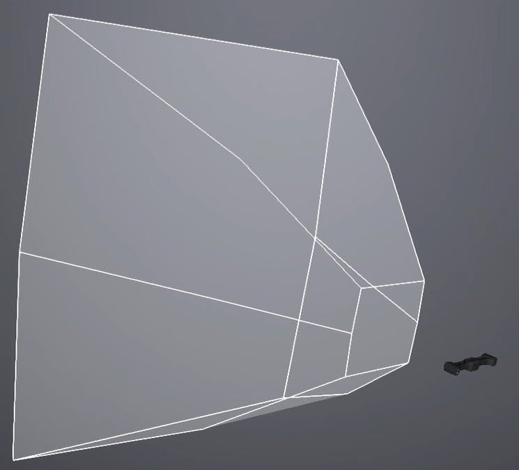
Tracking Volume
WHen enabled, the tracking volume will be visualized in the 3D scene, allowing you to see the relative positions of the tracker and the object being scanned. During scanning, you can use this function to adjust the position of the tracker to ensure that the object being scanned is within the tracking volume.
Caution
If you move the tracker in a real-world scene, the model position of the tracker in the 3D scene will not change, but the relative position of the scanned object in the 3D scene will change in real-time.
Intelligent Resolution
After enabling Intelligent Resolution, the software automatically adjusts the mesh resolution based on the curvature of the scanned object. Multiple scans are required during the scanning process to acquire high-quality data and clearer features of the scanned object. After enabling it and generating mesh, click Apply in the Mesh Processing interface to view the intelligent resolution effect: areas with high curvature will have higher data density.
Note
Intelligent Resolution is only available for Scan Mesh.