Interface
Function Preview
Note
The screenshot shown above is for illustrative purposes only. Always refer to the actual software interface.
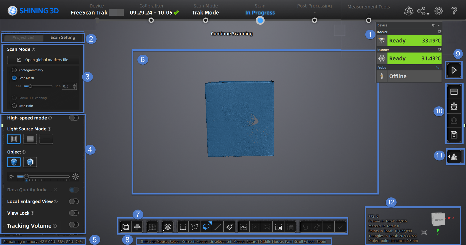
① Device Information Card
Click Device in the upper right corner of the software interface to expand the device information card, where you can view the device status. When the device warm-up is complete, the device card will display green; during the warm-up, it will show orange; if the device is not connected, it will display gray. If the probe is connected, it will also show the status of the probe.
Note
Please start the calibration or scanning only after the device has completed warm-up and the status shows Ready on the device information card.
| Icon | Icon | ||
|---|---|---|---|
| Click to open the device connection guide. | Displays the current battery battery level of the device. | ||
| The device is wirelessly connected. | The device is already connected with the wire. | ||
| Click to disconnect the paired probe when connected wirelessly. | Click to open the probe settings window. | ||
| Check the paired probe serial number. | The probe is wirelessly connected. | ||
| L1 of L-type. | L2 of L-type. | ||
| The length of the vertical tip. | The diameter of the current probe. |
② Project Group and Scan Setting
To manage your project group and set scanning parameters.
③ Scan Mode
You can choose Trak Mode or Laser Mode for scanning based on the application scenario.
To switch among Scan Mesh, Partial HD Scanning,Scan Global Markers / Photogrammetry and AI Feature Recognition.
Note
Photogrammetry is only supported when selecting Trak Mode (real-time scanning).
④ Parameter Settings
See more details in Parameter Settings.
⑤ Remaining Memory, CPU Usage and GPU Usage
- Remaining Memory: To display the percentage of remaining memory.
- CPU Usage: To display the CPU Usage of the computer in real time. You may need to close other unrelated software if it is too high.
- GPU Usage: To display the GPU Usage of the computer in real time.
⑥ Preview / Scanning Window
To preview the model and check the scanned model.
⑦ Data Editing
To edit data after scanning. See more details in Data Editing.
⑧ Keyboard Shortcuts
To change the perspectives and move the model by the composition of keys.
⑨ Buttons
Click ![]() to preview the scanning; click
to preview the scanning; click ![]() to start scanning; click
to start scanning; click ![]() to pause scanning.
to pause scanning.
⑩ Function
To import the project file and to align, delete and save the model data.
⑪ Mesh
To mesh the data; see more details in Mesh Processing.
⑫ Others
Display FPS, frame amount, point amount of the project and other information.
| Function | |
|---|---|
Fit View |
Click |
View controller |