Edentulous cases
By scanning the resting face and recording the edentulous motion, the software can determine the jaw relation.
Scanning process
Resting face is the face when the patient is fully relaxed and the jaw is in its resting position.
Steps
-
Instruct the patient to adjust their facial position, keeping their face relaxed with a slight mouth opening, maintaining a stable expression, and staying at an appropriate distance from the camera.
- Facial recognition: center the face in the camera and the face detection box will be green.
- Appropriate distance: adjust the distance between the face and camera untill the vertical indicator shows Suitable.
-
Scanning begins automatically after a 3-second countdown. To start manually, press the Space or click
 .
. -
Instruct the patient to slowly and steadily turn their head up, down, left, and right, or hold the scanner yourself and move it in the same directions to scan the patient’s head, depending on the mode you choose.
Col
Col
-
Click
 to finish scanning Resting Face.
Edentulous motion is used to collect the motion trajectory of markers to check the occlusion relationship.
Scanning process
Collect data of markers' positions and align with the static face data. Thus, the edentulous motion can be aligned with the whole face.
Preparations
- Use 97% alcohol pads to disinfect the markers.
- Assist the patient in wearing a mouth retractor or using a mouth opener to keep mouth open.
Steps
-
With the patient’s mouth open, dry the tooth surfaces with cotton balls or an air syringe.
-
Select a suitable Jaw Motion Tracker for the patient. After proper placement, click Confirm.
Col
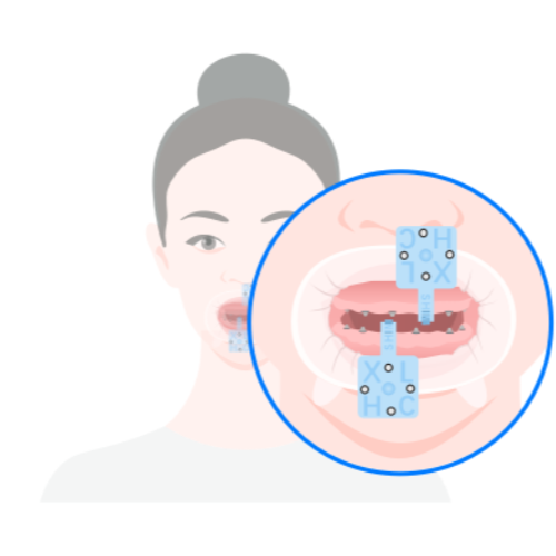 Edentulous Jaw Motion Tracker
(Select this option for the patient with implants)Col
 Dentulous Jaw Motion Tracker
(Select this option for the patient with denture base or denture)Caution
- Please fix Featured Shell before using Jaw Motion Tracker and place markers.
- Please fix Dentulous Jaw Motion Tracker and the denture base with light-curing resin or temporary dental materials.
-
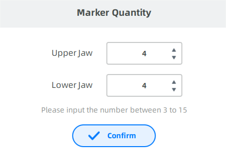
Click Start, and enter the marker quantity to collect two sets of marker data.
-
Keep the head steady.
-
The scanner's camera will automatically count the markers and record the number.
Note
-
If the number of markers is consistent with the number you punched in, the camera will automatically save the coordinates of points when the maxillary and mandibular teeth approach each other.
-
If the number of markers is not consistent with the number you punched in, adjust the face position or re-attach the points.
-
-
Open your mouth slightly. The camera will automatically recognize the number of markers on the upper and lower jaw again.
-
When finished, a message will pop up to inform that marker input is completed.
-
Preparation
- Ensure that the patient is putting on the Tracker in place.
- Ensure that the markers are securely attached to prevent them from falling off.
Steps
-
Adjust the face position.
- Face recognition: center the face in the camera and the face detection box will be green.
- Marker recognition: ensure markers are identified as green.
- Appropriate distance: adjust the distance between the face and camera untill the vertical indicator shows Suitable.
-
The software automatically starts scanning after 3 seconds when the face distance from the camera is suitable. Or click
to start scanning directly. -
Instruct the patient to slowly and steadily turn their head up, down, left, and right, or hold the scanner yourself and move it in the same directions to scan the patient’s head, depending on the mode you choose.
Col
Col
-
Click
to finish scanning static face.
Caution
During the scan, the patient should maintain a stable facial expression.
Note
Since jaw motion alignment process may take a long time, it's better to perform opening-closing movement first to prevent marker from being soaked by saliva, resulting in recognition failure.
Preparation
- Ensure that the patient is putting on the Tracker in place.
- Ensure that the markers are securely attached to prevent them from falling off.
Steps
-
Instruct the patient to align the face with the detection box.
-
Scanning begins automatically after a 3-second countdown. To start manually, press the Space or click
. -
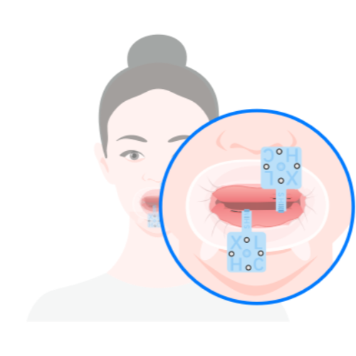
Instruct the patient to perform the opening-closing movement:
- Perform the opening-closing action qucikly with mouth opens slightly.
- Complete at least 30 full opening-closing movements.
- Keep the rest of the face as still as possible.
-
After completing the required times of opening-closing movements, click the
button to end the scan. -
The software will automatically save the recorded opening-closing movement trajectory.
Post-scan operations
- Carefully remove the markers on the tracker, then take out the tracker.
- Replay and review the opening-closing movement trajectory in the interface.
Caution
Be sure to remove the markers before taking out the tracker to prevent the markers from accidentally falling into the mouth.
Related operations
| Icon | Description |
|---|---|
| Previous frame | |
| Play | |
| Next frame | |
| 1X ▲ | Select playback speed |
| Replay | |
| View occlusion | |
| Open the bite |
The rest position is the natural, relaxed posture of the mandible when the muscles of mastication are at rest and there is no conscious effort to maintain a specific jaw position.
Steps
-
Instruct the patient to align the face with the detection box.
-
Instruct the patient to relax the facial muscles and close the lips naturally.
-
Ask the patient to look straight ahead and clear mind. This will help the lower jaw relax into its natural position.
-
Observe the patient's facial expression to ensure they are relaxed and there is no tension in the jaw.
-
Click
 to record the rest position of the mandible.
 -
A message will appear confirming that the rest position has been recorded successfully.
Note
- Ensure the patient is comfortable and relaxed.
- Avoid instructing the patient to consciously control their jaw position.
- Maintain a quiet environment during the recording process.
The alignment includes two groups of data (the alignment of upper jaw and static face and the alignment of lower jaw and static face). Choose automatic alignment first. If the results are unsatisfactory, switch to manual alignment.
Note
If the intraoral data of the patient has not been imported during order creation, click  on the right side of the interface, and select the corresponding upper and lower jaw data for import.
Steps
-
Click
 to enter the interface.
 -
Click
to import upper jaw data and lower jaw data. -
Start alignment.
Auto alignment Manual alignment Click  and the software will automatically align the data.
Select Manual alignment if the alignment effect is not ideal.Steps
1) Click to start manual alignment.
2) Double-click on the upper/lower jaw and the static face respectively to select 3 corresponding points.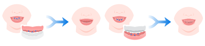
3) Click to confirm.
 Caution
Those added points should not be in one straight line. -
Click
 to check the alignment effect.
Face alignment contains 3 steps: the alignment of upper jaw and static face, the alignment of lower jaw and static face and the alignment of the resting face and static face.
Align the upper jaw and the static face.
| Auto alignment | Manual alignment |
|---|---|
| Click and the software will automatically align the data. Select Manual alignment if the alignment effect is not ideal. |
Steps 1) Click to start manual alignment. 2) Double-click on the upper jaw and the static face respectively to select 3 corresponding points. 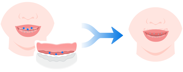 3) Click to confirm.CautionThose added points should not be in one straight line. |
Click to check the alignment effect.
Align the lower jaw and the static face.
| Auto alignment | Manual alignment |
|---|---|
| Click and the software will automatically align the data. Select Manual alignment if the alignment effect is not ideal. |
Steps 1) Click to start manual alignment. 2) Double-click on the lower jaw and the static face respectively to select 3 corresponding points. 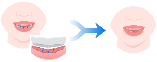 3) Click to confirm.CautionThose added points should not be in one straight line. |
Click to check the alignment effect.
Align the resting face data with the static face containing the dental retractor. Click Resting face and Static facial on the left.
| Auto alignment | Manual alignment |
|---|---|
| Click and the software will automatically align the data. Select Manual alignment if the alignment effect is not ideal. |
Steps 1) Click to start manual alignment. 2) Double-click on the resting face and the static face respectively to select 3 corresponding points. 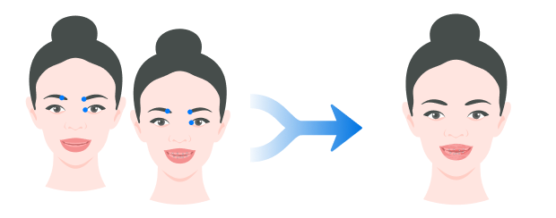 3) Click to confirm.CautionThose added points should not be in one straight line. |
Click to check the alignment effect.
Optimal jaw relation
To determine the optical jaw relation of edentulous jaw, there are 3 steps: create an axis, confirm the vertical distance and analyze the horizontal relationship.
FScan can recognize the feature points on the model automatically.
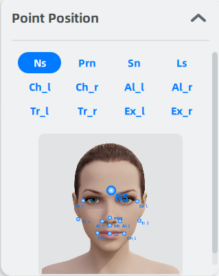
If some point fail to be recognized, you can add the point to its corresponding position according to the prompt on the right.
Point Marking
Create an axis according to the facial feature points.
| Point | Illustration | Description | |
|---|---|---|---|
| Point A | 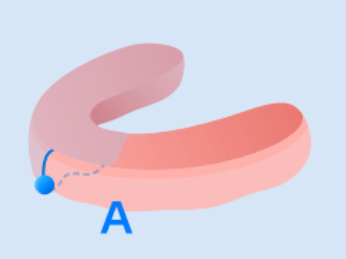 |
The lowest point of the intersection between the upper jaw and the median sagittal plane. Point A is the origin of the axis. | |
| Point B | 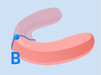 |
The highest point of the intersection between the lower jaw and the median sagittal plane. |
Manual adjustment
-
Move the cursor to the point and when the point turns into red, press the point and move it. Or double-click on the intersection line of the gingiva for quick movement.
-
After adjusting, click
to confirm and create an axis.
Create a plane which is 2 mm (default value, adjustable based on clinical conditions) higher than Point C (the highest point of the incisal edge of the mandibular central incisor on the midsagittal plane) and perpendicular to the Z axis.
Enter the distance between the plane and Point C to adjust the plane. Or press the plane and move to adjust it. Click to confirm.
If you want to hide the trajectory and axis, click ![]() , and click
, and click ![]() before the corresponding name.
before the corresponding name.
The software will automatically analyze the intersection between the relative movement trajectory (the trajectory of habitual opening and closing the mouth) of Point B and the horizontal plane. And then the software will calculate the trend of the intersections and determine the horizontal jaw relationship.
![]() Myofascial point refers to the position with the highest repeatability of the lower jaw motion at the set vertical distance.
Myofascial point refers to the position with the highest repeatability of the lower jaw motion at the set vertical distance.
![]() Centric relation position refers to the most rearward position of the lower jaw motion at the set vertical distance.
Centric relation position refers to the most rearward position of the lower jaw motion at the set vertical distance.
![]() —
— ![]() The distance between the myofascial point and the centirc relation position. It is considered as dependable when it is no more than 2 mm.
The distance between the myofascial point and the centirc relation position. It is considered as dependable when it is no more than 2 mm.
You may need to adjust the arch line if it fails to be generated automatically or its effect is unsatisfactory.
There are two ways to enter the arch line adjustment interface:
- The software prompts that arch line generation has failed, and requests that you need to manually add six points. Then click OK to enter the tooth arch adjustment interface.
- Click the
 next to the Tooth Adjustment title.
Once in the arch line adjustment interface, follow these steps:
- Locate the alveolar ridge on the model.
- Click six times in sequence along the ridge to add six points.
- After adding the sixth point, the software will automatically generate the arch line.
Note
- To delete a point, right-click on it.
- To confirm the arch line, click the .
- If unsatisfied, click the
 to readjust.
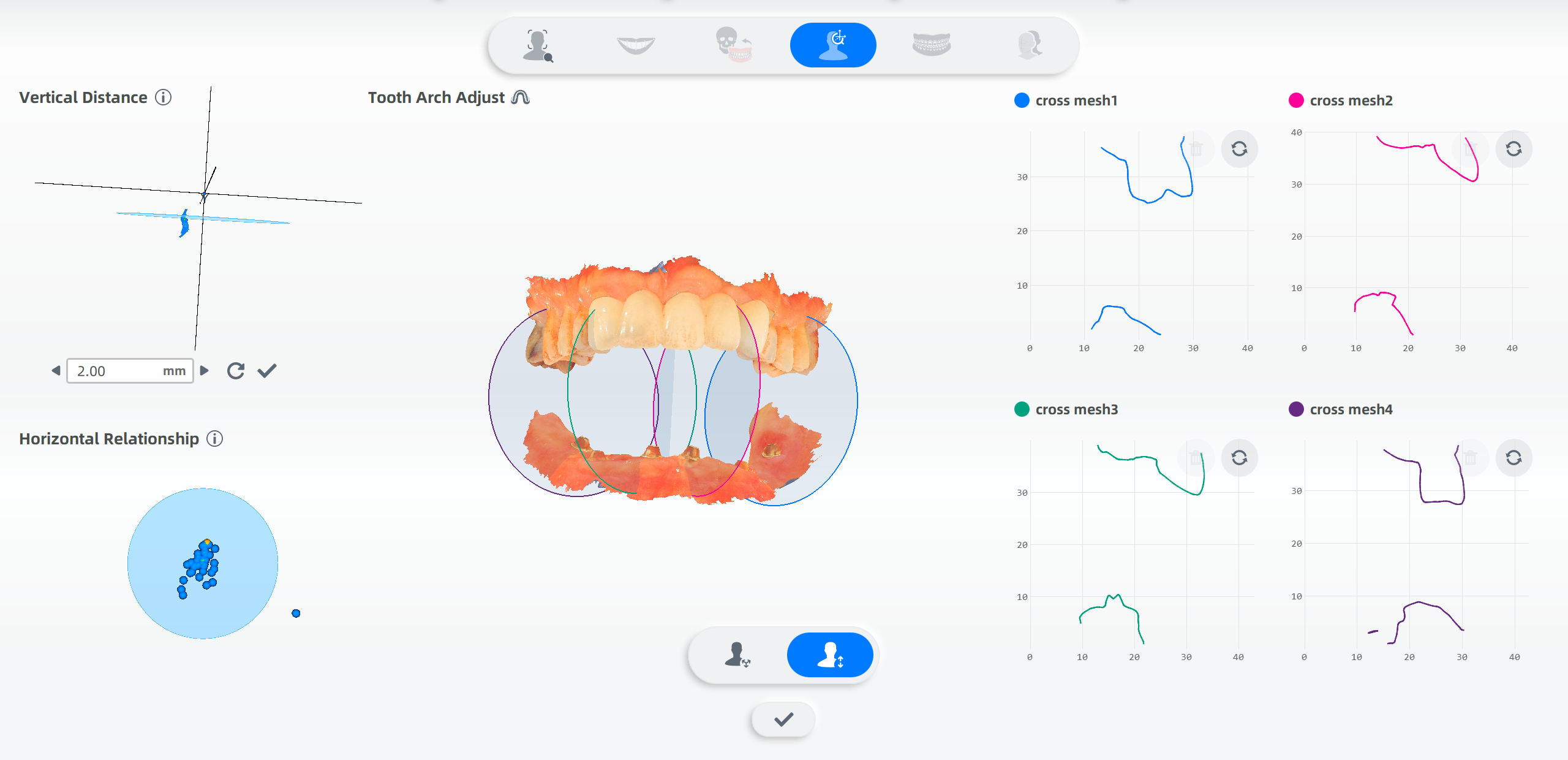
The software will automatically generate four circular planes distributed along the dental arch based on vertical distance. These planes intersect with the upper and lower jaws to form sections.
Within each section, click on the upper and lower jaw contours to generate measurement points. A line will automatically form between two measurement points, displaying the straight-line distance between them.
Note
Adjusting the position of circular planes on the model will regenerate the corresponding section.