Edentulous cases
Scanning process
Recognize the coordinates of the markers for the alignment with face data.
Preparation
- Disinfect the markers with a 75% alcohol swab and clean the patient's teeth surface to remove plaques.
- Assist the patient in wearing a disposable mouth retractor to maintain an open state.
Steps
-
With the patient’s mouth open, dry the surface of the teeth with dry cotton balls or an air syringe.
-
Select Edentulous Jaw Motion Tracker or Dentulous Jaw Motion Tracker and prepare the patient for scanning. Once the patient is ready, click Confirm.
Col
 Edentulous Jaw Motion Tracker
(For the patient with implants)Col
 Dentulous Jaw Motion Tracker
(For the patient with a denture base or denture)Caution
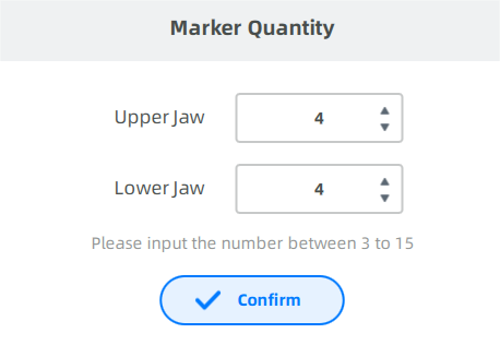
- More than 4 markers are required.
- Markers cannot be sticked in an approximate straight line.
-
Please fix Featured Shell before using Jaw Motion Tracker and place markers.
-
Please fix Dentulous Jaw Motion Tracker and the denture base with light-curing resin or temporary dental materials.
-
Enter the number of markers placed, click Confirm, to collect two sets of marker data.
-
Choose
 Handheld Mode or
  Fixed Mode in the lower left corner of the interface.
Description
The default is handheld mode. In fixed mode, the camera window mirrors the scan.
-
Start scanning:
-
Instruct the patient to keep the head still and maintain a stable expression. Ensure that the upper and lower jaws are in an occlusal state.
-
The scanner's camera will automatically count the markers and record the number.
Note
-
If the number of markers recognized by the camera matches the input number, the coordinates of the markers are automatically saved.
-
If the number of markers does not match the input number, adjust the facial position or place the markers again.
-
If recognized markers turn orange, please check the scanning angle and ensure the markers are not be covered, moved, or wet. If you find any problem, please reattach the markers or recalibrate the device.
-
-
Tell the patient to open the mouth slightly. The camera will automatically recognize the number of markers on the upper and lower jaw again.
-
Preparation
-
Ensure the patient is still wearing the tracker, with the upper and lower jaws in the rest position.
-
Ensure that the markers are securely pasted to avoid falling off during the scanning process.
Steps
-
Adjust the facial position:
- Face recognition: The face is centered, and the face detection box shows green.
- Markers recognition: Ensure the markers are recognized as green.
- Appropriate distance: The distance indicator shows Suitable.
-
Maintain a stable facial position and prepare to start scanning:
- Handheld mode: Press Space or click
 to start scanning.
 - Fixed mode: Scanning starts automatically after a 3-second countdown or can be started manually, similar to the handheld mode.
Note
The countdown guide for handheld mode is turned off by default and can be enabled in Scan Settings.
- Handheld mode: Press Space or click
-
In handheld mode, you need to move the scanner up, down, left, and right to scan the patient's head; in fixed mode, guide the patient to slowly and evenly rotate their head up, down, left, and right.
Col
Handhold ModeCol
Fixed Mode -
Press Space again or click
 to end the scan.
 -
After the scan is completed, the software will automatically align the scanned model and oral scan model to obtain the oral scan model in the rest position.
-
Automatic alignment successful:
- The heat map is displayed by default to check the alignment effect; click
 will hide the heat map.
 - If you are not satisfied with the alignment effect, you can click
 to go to the Data Alignment to align them again.
 - If you are not satisfied with the facial scanning effect, you can click to rescan.
- The heat map is displayed by default to check the alignment effect; click
-
Automatic alignment failed:
The interface will prompt that alignemnt has failed, and you need to go to the Data Alignment for manual alignment.
-
-
Click
to go to the next process.
To prevent inaccurate trajectory data caused by patient's habitual mandibular protrusion, guide the mandible into centric relation by Dawson's bilateral manipulation technique before tracking the opening-closing movement:
- Recline the patient all the way back.
- Stabilize the head.
- After the head is stabilized, lift the patient's chin again to slightly stretch the neck.
- Gently position four fingers of each hand on the lower border of the mandible.
- Bring thumbs together to form a C with each hand. Ensure that the fingers are properly positioned.
- With a very gentle touch, manipulate the jaw so it slowly hinges open and closed.
- After the mandible feels like it is hingeing freely and the condyles seem to be fully seated up in their fossae, assume that the mandible is in centric relation.
Preparation
- Ensure that the patient is still wearing the retractor.
- Ensure that the markers are securely pasted to avoid falling off during the scanning process.
Steps
-
Adjust the patient's facial position to align with the face detection box in the interface. When correctly aligned, the box will display in green.
-
Maintain a stable facial position and prepare to start scanning:
- Handheld mode: Press Space or click to start scanning.
- Fixed mode: Scanning starts automatically after a 3-second countdown or can be started manually, similar to the handheld mode.
Note
The countdown guide for handheld mode is turned off by default and can be enabled in Scan Settings.
- Handheld mode: Press Space or click
-
Instruct the patient to perform the opening-closing movement:
- Perform the opening-closing action qucikly with mouth opens slightly.
- Complete at least 30 opening-closing movements.
- Keep the rest of the face as still as possible.
Note
The reference model is shown in green overlay to help you access the stability of jaw position during the movement.
-
Press Space again or click
to end the scan. -
The software will automatically process the alignment of the static face and the markers/tracker, and after completion, it will redirect to the Static Face scanning process.
-
You can return to the interface to view the recorded trajectory, or proceed to the next process.
Related Operations
| Icon | Description |
|---|---|
| Previous frame | |
| Play | |
| Next frame | |
| 1X | Select playback speed |
| Replay | |
| View occlusion | |
| Open the bite |
Note
Please remove the tracker before scanning the resting face.
Steps
-
Instruct the patient to adjust their facial position, keeping the face relaxed with a slightly open mouth and a stable expression, while maintaining an appropriate distance from the camera.
- Face recognition: Face is centered, and the face detection box is displayed in green.
- Appropriate distance: The distance indicator shows Suitable.
-
Maintain a stable facial position and prepare to start scanning:
- Handheld mode: Press Space or click to start scanning.
- Fixed mode: Scanning starts automatically after a 3-second countdown or can be started manually, similar to the handheld mode.
Note
The countdown guide in handheld mode is turned off by default and can be enabled in Scan Settings.
- Handheld mode: Press Space or click
-
In handheld mode, you need to move the scanner up, down, left, and right to scan the patient's head; in fixed mode, guide the patient to slowly and evenly rotate their head up, down, left, and right.
Col
Handheld modeCol
Fixed mode -
Press Space again or click
to end the scan. -
Click Data Alignment to align the resting face with the static face.
| Auto alignment | Manual alignment |
|---|---|
| Click Click |
Steps 1) Click 2) Click on the upper jaw and the static face respectively to select 3 ~ 12 corresponding points. 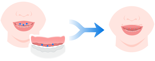 3) Click  to confirm. to confirm. Caution CautionThose added points should not be in one straight line. |
Click  to check the alignment effect.
| Auto alignment | Manual alignment |
|---|---|
| Click Click |
Steps 1) Click 2) Click on the lower jaw and the static face respectively to select 3 ~ 12 corresponding points. 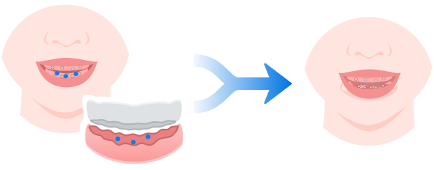 3) Click to confirm.CautionThose added points should not be in one straight line. |
Click to check the alignment effect.
| Auto alignment | Manual alignment |
|---|---|
| Click Click |
Steps 1) Click 2) Click on the resting face and the static face respectively to select 3 ~ 12 corresponding points. 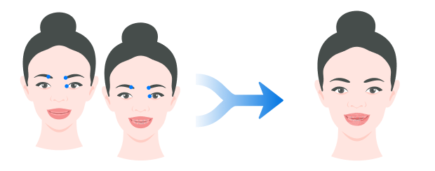 3) Click to confirm.CautionThose added points should not be in one straight line. |
Click to check the alignment effect.
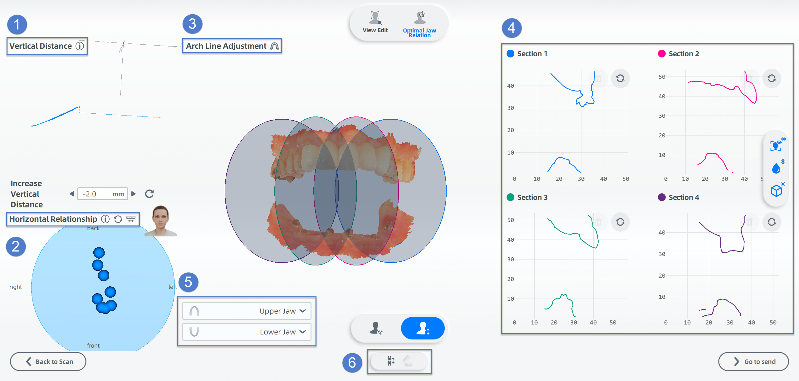
Optimal jaw relation
To determine the optimal jaw relation of edentulous jaw, there are 3 steps: create an axis, confirm the vertical distance and analyze the horizontal relationship.
FScan can recognize the feature points on the model automatically.
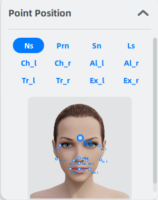
If some points fail to be recognized, you can add the point to its corresponding position according to the prompt on the right.
Point marking
Create an axis according to the facial feature points.
| Point | Illustration | Description | |
|---|---|---|---|
| Point A | 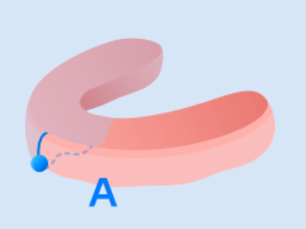 |
The lowest point of the intersection between the upper jaw and the median sagittal plane. Point A is the origin of the axis. | |
| Point B | 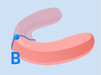 |
The highest point of the intersection between the lower jaw and the median sagittal plane. |
Manual adjustment
-
Move the cursor to the point and when the point turns into red, press the point and move it. Or double-click on the intersection line of the gingiva for quick movement.
-
After adjusting, click
to confirm and create an axis.
Create a plane which is 2 mm (default value, adjustable based on clinical conditions) higher than Point C (incisal point of the lower jaw in the rest position.) and perpendicular to the Z axis.
Enter the distance between the plane and Point C to adjust the plane. Or press the plane and move to adjust it.
If you want to hide the trajectory and axis, click ![]() , and click
, and click ![]() before the corresponding name.
before the corresponding name.
The software will automatically analyze the intersection between the relative movement trajectory (the trajectory of Opening-and-Closing Movement) of Point B and the horizontal plane. And then the software will calculate the trend of the intersections and determine the horizontal jaw relationship.
![]() Myofascial point refers to the position with the highest repeatability of the lower jaw motion at the set vertical distance.
Myofascial point refers to the position with the highest repeatability of the lower jaw motion at the set vertical distance.
![]() Posterior contact point refers to the most rearward position of the lower jaw motion at the set vertical distance.
Posterior contact point refers to the most rearward position of the lower jaw motion at the set vertical distance.
![]() —
— ![]() The distance between the myofascial point and the posterior contact point. It is considered as dependable when it is no more than 2 mm.
The distance between the myofascial point and the posterior contact point. It is considered as dependable when it is no more than 2 mm.
Points: the total number of myofascial points and posterior contact point.
Reset the display ratio of Horizontal Relationship to the initial state.
If enabled, clicking two points (a myofascial point or a posterior contact point) will automatically create a straight line between them, with the length of the line displayed beside the icon.
You may need to adjust the arch line if it fails to be generated automatically or its effect is unsatisfactory.
There are two ways to enter the arch line adjustment interface:
- The software prompts that arch line generation has failed, and requests that you need to manually add six points. Then click OK to enter the tooth arch adjustment interface.
- Click the
 next to the Tooth Adjustment title.
Once in the arch line adjustment interface, follow these steps:
- Locate the alveolar ridge on the model.
- Click six times in sequence along the ridge to add six points.
- After adding the sixth point, the software will automatically generate the arch line.
Note
- To delete a point, right-click on it.
- To confirm the arch line, click the .
- If unsatisfied, click the
 to readjust.
The software will automatically generate four circular planes distributed along the dental arch based on vertical distance. These planes intersect with the upper and lower jaws to form sections.
Within each section, click on the upper and lower jaw contours to generate measurement points. A line will automatically form between two measurement points, displaying the straight-line distance between them.
Note
Adjusting the position of circular planes on the model will regenerate the corresponding section.
Select other models of upper or lower jaw from the drop-down list.
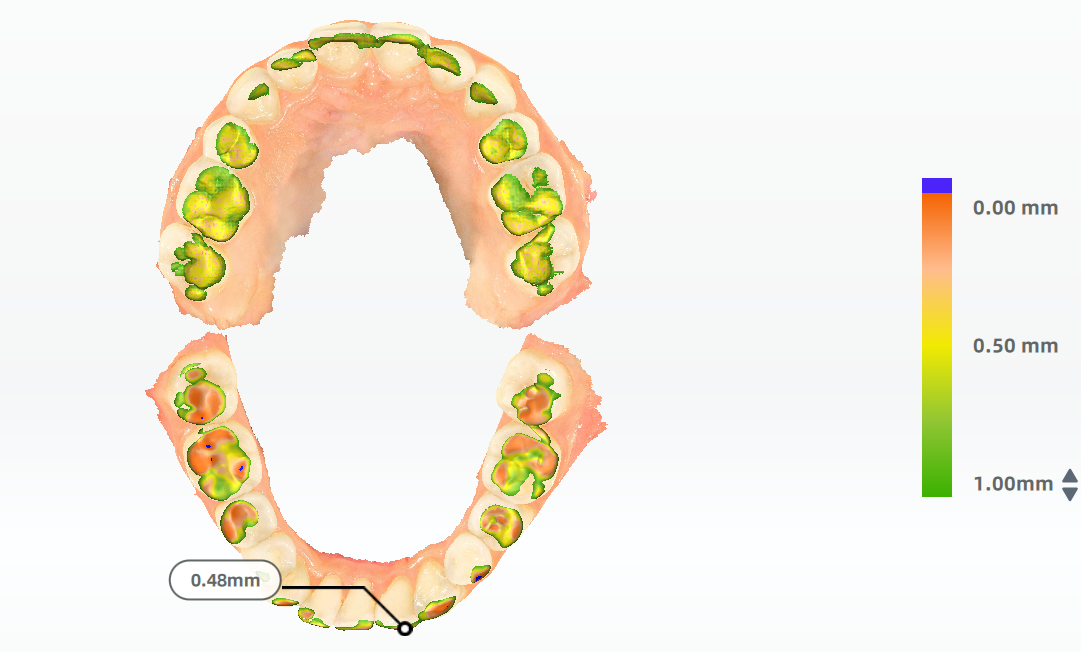
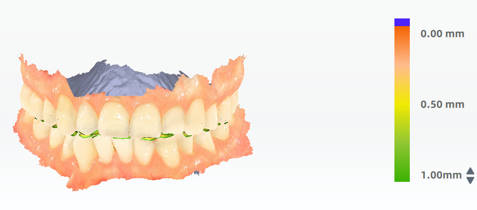
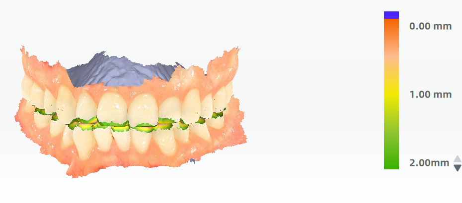
You can check the occlusion with color indications and the specific value.
-
Click
 , and then the model is colored to indicate the occlusion.
Color Indications Green Area with a large separation Red Area with a smaller separation Blue Bite-through area -
To adjust the range of depth displayed on the model, click ▲/▼ beside the color map.
Col
Default valueCol
Maximum value
Switch the display mode. This function is available only when viewing occlusion. Click ![]() to view the top-down occlusal view.
to view the top-down occlusal view.