Point
In the Create Features toolbar, click ![]() Point to expand the drop-down list, where you can select
Point to expand the drop-down list, where you can select ![]() CMM,
CMM, ![]() Anchor,
Anchor, ![]() Extreme Position,
Extreme Position, ![]() Numerically,
Numerically, ![]() From Features and
From Features and ![]() From Cross-Section creation methods.
From Cross-Section creation methods.
Extraction
If the created feature is a reference feature, the corresponding measured feature can be extracted automatically or manually.
Note
Except for the From Features method, other creation methods support directly specifying features as reference features or measured features. If you define a feature as a reference feature, after importing at least one measurement model, you can extract the measured feature to generate feature pairs.
- Automatic Extraction: Enable Auto Extraction of Measured Values via
 Settings in the upper right corner of the software interface or check
  Extract Measured Feature in the creation window. The software will automatically extract the corresponding measured feature with default parameters after creating any reference feature.
 - Manual Extraction: After creating a reference feature, right-click the feature group in the tree view on the left, select Extract Measured Feature and specify the measurement model to be extracted; you can specify Align Object in the extraction pop-up window.
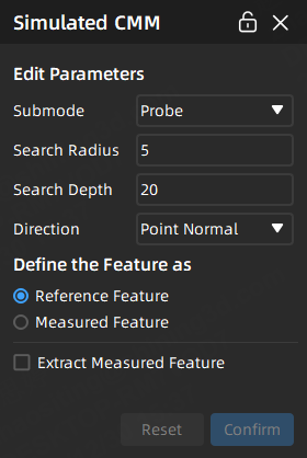
CMM
Simulate the rectangle, probe and disk contact methods of an actual Coordinate Measuring Machine (CMM) probe1 to create point features.
Note
- Before creating point features using the CMM method, please import a reference model or a measured model.
- If you choose the submode as rectangle, please ensure the selected created plane can not be vertical with the search direction.
The steps for creating point features through CMM are as follows:
Col
- Select
 CMM in the drop-down list of
  Point to open the corresponding window.
 - Select a submode:
- Rectangle: Select a constraint plane (XY plane / XZ plane / YZ plane / a created plane feature), customize the search depth (mm), length (mm) and width (mm), select a direction (point normal / X axis / Y axis / customize), and define the feature as Reference Feature or Measured Feature.
- Probe or Disk: Select a direction (point normal / customize), customize the search radius (mm) and search depth (mm), and define the feature as Reference Feature or Measured Feature.
- After completing relevant settings, you can click on the model in the 3D scene to create points; then click Confirm to create the
 reference points or
  measured points.
Col
Anchor
Directly anchor points on the model to create point features.
Note
- Before creating point features using the anchor method, please import a reference model or a measured model.
The steps for creating point features through anchor are as follows:
- Select
 Anchor in the drop-down list of Point to enable the anchor tool.
 - Click on the model in the 3D scene and define the feature as the Reference Feature or Measured Feature; then click Confirm in the Anchor window to create reference point or measured point.
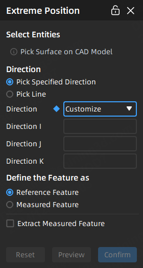
Extreme Position
Usually, when inspecting irregular workpieces, it is necessary to measure distances between two extreme positions. In such cases, you can use this feature to create point features at the extreme positions.
Note
Before creating point features using the extreme position method, please import a reference model.
The steps for creating point features through extreme position are as follows:
Col
- Select
 Extreme Position in the drop-down list of Point to enable the extreme position tool.
 - Click on the CAD model in the 3D scene to pick a surface where the extreme position points need to be created, and this surface wil be determined as the calculation region.
- Select direction in the window of Extreme Position:
- Pick specified direction: support customizing direction or selecting X / Y / Z axis, and define the feature as reference or measured feature.
- Pick line: select a created line feature and define the feature as reference or measured feature.
- After completing relevant settings, click Preview to preview the extreme position point to be created; then click Confirm to create the reference point or measured point.
Col
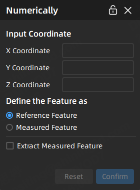
Numerically
Customize the coordinates of points to create point features.
Note
Before creating point features using the anchor method, please import a reference model or a measured model.
The steps for creating point features numerically are as follows:
Col
- Select
 Numerically in the drop-down list of Point to open the corresponding window.
 - Input X coordinate, Y coordinate and Z coordinate and define the feature as reference or measured feature.
- After completing relevant settings, you can preview the point feature in the 3D scene; then click Confirm to create the reference point or measured point.
Col
From Features
Create new point features based on created features.
Note
- Before creating point features using this method, please import a reference model or a measured model, and ensure that there exists the corresponding features.
- This method does not support defining features: If the selected feature is a reference or measured feature, the new created feature can only be a reference or measured feature.
- If a reference feature is created, then you can extract the measured feature to generate feature pairs before importing at least one measured model.
The steps for creating point features from features are as follows:
-
In the drop-down list of
Point >  From Features, select the corresponding creation method.
Creation Method Description Point Average Creates a new point feature by calculating the average value of the selected points.  Note
Note
If the selected feature pairs include reference features but some do not have measured features, the created feature will only have reference values without measured values.From Sphere Center Creates a new point feature based on the center of the selected sphere. From Circle Center Creates a new point feature based on the center of the selected circle. Slot Center Point Creates a new point feature based on the center of the selected slot. Cone Vertex Creates a new point feature based on the vertex of the selected cone. Line Start Point and Offset Creates a new point feature based on the start point of the selected line, and the position of the point can be adjusted by entering an offset value. Note
Input numbers with up to 3 decimal places after the decimal point and a maximum of 13 digits before the decimal point in Offset; positive values indicate offset along the normal direction, while negative values indicate offset in the opposite direction. -
Select the corresponding created features, and click Confirm to create the feature, which will be displayed with the
 icon in the
  feature module of the left-side tree view.
From Cross-Section
Directly anchor points on the cross-section to create point features.
Note
- Before creating point features using the from cross-section method, please import a reference model or a measured model.
- This method supports specifying features as reference features or measured features.
- If you Define the Feature as Reference Feature, then you can extract the measured feature to generate feature pairs before importing at least one measured model.
The steps for creating point features from cross-section are as follows:
- Select
 From Cross-Section in the drop-down list of Point to open the corresponding window.
 - Select an existing cross-section feature, and define the feature as the reference or measured feature.
-
After completing relevant settings, you can click on the cross-section in the 3D scene to create; then click Confirm in the From Cross-Section window to create the
reference point or measured point.Note
When you move the cursor over the line of the cross-section, you can preview the feature point in real-time. After creation, you can drag the feature point along the current line to adjust its position.
-
A CMM probing system generally consists of a probe head and a touch-trigger probe. The probe makes slight contact with the surface of the measured workpiece, and by measuring the position of the probe in a three-dimensional coordinate system, the coordinates of the measurement points on the workpiece are obtained. ↩