Slot
In the Create Features toolbar, click ![]() Slot to expand the drop-down list, where you can select
Slot to expand the drop-down list, where you can select ![]() Pick on CAD Model,
Pick on CAD Model, ![]() Anchor,
Anchor, ![]() Numerically,
Numerically, ![]() Fit and
Fit and ![]() From Cross-Section creation methods.
From Cross-Section creation methods.
Extraction
If the created feature is a reference feature, the corresponding measured feature can be extracted automatically or manually.
Note
Except for the From Features method, other creation methods support directly specifying features as reference features or measured features. If you define a feature as a reference feature, after importing at least one measurement model, you can extract the measured feature to generate feature pairs.
- Automatic Extraction: Enable Auto Extraction of Measured Values via
 Settings in the upper right corner of the software interface or check
  Extract Measured Feature in the creation window. The software will automatically extract the corresponding measured feature with default parameters after creating any reference feature.
 - Manual Extraction: After creating a reference feature, right-click the feature group in the tree view on the left, select Extract Measured Feature and specify the measurement model to be extracted; you can specify Align Object in the extraction pop-up window.
Pick on CAD Model
Create slot features by directly clicking on the geometric features shaped as slots of the CAD model.
Note
- Before creating slot features using the CAD auto creation method, please import a reference model.
- This method supports specifying features as reference features or measured features.
- If you Define the Feature as Reference Feature, then you can extract the measured feature to generate feature pairs before importing at least one measured model.
- You can also use the
 CAD Auto Create method in the Assisted Feature Creation toolbar to automatically create features.
The steps for creating slot features through picking on CAD model are as follows:
- Select
 Pick on CAD Model in the drop-down list of
  Slot to open the corresponding window.
 - Click on the highlighted slot feature of the model in the 3D scene to create, and define the feature as Reference Feature or Measured Feature in the window of Pick on CAD Model.
- Click Confirm to create the
 reference slot or
  measured slot, which will be displayed in the
  feature module of the left-side tree view.
Anchor
Directly anchor points on the model to create slot features.
Note
Before creating plane features using the anchor method, please import a reference model or a measured model.
The steps for creating plane features through anchor are as follows:
- Select Anchor in the drop-down list of Slot to enable the anchor tool.
-
Click to add 4 points on the model in the 3D scene and define the feature as the Reference Feature or Measured Feature; then click Confirm in the Anchor window to create the
reference slot or measured slot.Note
Any three added points must not be collinear.
Numerically
Note
- This method supports specifying features as reference or measurement features.
- Before creating slot features using the numerically method, please import the reference model or measurement model first.
- If defining the feature as a reference feature, at least one measurement model must be imported before extracting measurement features to generate feature pairs.
The steps to create slot features using the numerically method are as follows:
- Select Slot from the dropdown list and choose
 Numerically to open the corresponding window.
 - Customize the X / Y / Z coordinates, normal, angle, length, and width of the slot center point, and define the feature as a Reference Feature or Measurement Feature.
- Click Confirm to create the feature, which will then be displayed in the left directory tree under the Feature module as either a Slot Reference Object or Slot Measurement Object.
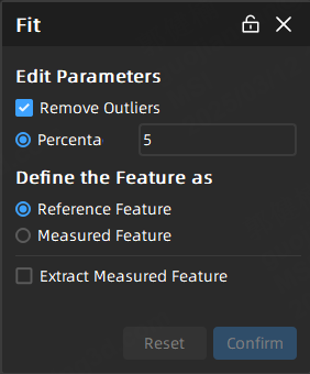
Fit
Create slot features by fitting geometric features shaped as slots through selecting points on the mesh model.
Note
- Before creating slot features using the fit method, please import a reference model or a measured model (meshed).
- This method supports specifying features as reference features or measured features.
- If you Define the Feature as Reference Feature, then you can extract the measured feature to generate feature pairs before importing at least one measured model.
The steps for creating slot features through fit are as follows:
Col
- Select
 Fit in the drop-down list of Slot to open the corresponding window.
 - Edit parameters including eliminate noise, as well as define the feature as reference feature or measured feature.
- After completing relevant settings, you can select tools in the toolbar under the 3D scene, and select areas to be fitted on the model; then click Confirm to create the reference slot or measured slot, which will be displayed in the feature module of the left-side tree view.
Col
The introduction to toolbar as well as shortcuts is as follows:
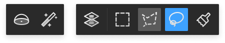
| Icon | Name | Description |
|---|---|---|
| Sphere | Select mesh vertices on the surface of the mesh model to choose the fitting region. Note NoteAfter enabling this function, other selection tools or the select through function can not be used. |
|
| Magic Wand | Automatically select adjacent areas on the mesh model according to curvature.Note |
|
| Select Through | Disabled by default, which means only visible surfaces can be selected; It can be enabled to select both the front and back regions of the model. | |
| Rectangle | Select / Deselect the data area in the form of |
|
| Polygon | Select / Deselect the data area in the form of |
|
| Lasso | Select / Deselect the data area in the form of |
|
| Brush | Use brush (support brush adjusting) to select / deselect the data area. |
| Function | Shortcut |
|---|---|
| Select | Shift+left-button |
| Deselect | Ctrl+left-button |
| Adjust the size brush | Shift+left-button |
Note
For more shortcuts, please refer to ![]() > Shortcut Instructions in the top right corner of the interface.
> Shortcut Instructions in the top right corner of the interface.
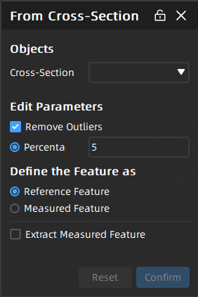
From Cross-Section
Create slot features based on existing cross-sections.
Note
- Before creating slot features using this method, please ensure that there exists at least one created cross-section.
- This method supports specifying features as reference features or measured features
- If you Define the Feature as Reference Feature, then you can extract the measured feature to generate feature pairs before importing at least one measured model.
The steps for creating slot features from cross-sections are as follows:
Col
-
Select
 From Cross-Section > Click on CAD section,
  Fit or
  Anchor in the drop-down list of Slot to open the corresponding window. Click on the CAD section: After selecting the cross-section, click on the reference cross-section, and then define the feature as a reference feature or measured feature in the window. Fit: After selecting the cross-section, click directly on the reference or measured cross-section, and then set whether to remove outliers in the window, and define the feature as a reference feature or measured feature. Anchor: After selecting the cross-section, click directly on 4 points along the cross-section line, and define the feature as a reference feature or measurement feature; the first 3 points determine the width and axial direction of the slot, while the last point determines the length and long axis direction of the slot.
 -
Click Confirm to create the line feature, which will be displayed in the
feature module of the left-side tree view.
Col