Mesh Editing
After meshing model, you can perform mesh editing, data editing and use some other functions.
Mesh Processing
In the Mesh Editing window on the left side of the interface, click ![]() for each optimization option to unfold the corresponding function panel.
for each optimization option to unfold the corresponding function panel.
Note
When using the stepper, you can directly enter the number or click ![]() to adjust the value.
to adjust the value.
| Optimization options | Description | Note |
|---|---|---|
| Simplification | Simplify the model data as the triangular mesh generated from the scan is in a large size. Drag the slider or use the stepper to set the ratio from 0 to 99. The default is 0, indicating no simplification. |
|
| Mesh Optimization | Restructure the mesh topology based on the mesh curvature and sharpen the surface features of scan data. Drag the slider or use the stepper to set the ratio from 0 to 100. The default value is 0, indicating no optimization. |
|
| Smooth | Smooth the possible noise on the surface of the scan data. Drag the slider or use the stepper to set the ratio from 0 to 100. The default value is 0, indicating no smooth. |
|
 to reset the value to default.
| Optimization options | Description | Note |
|---|---|---|
| Remove Small Floating Parts | Remove small floating parts isolated from the main data. Drag the slider or use the stepper to adjust the area of floating parts to be removed. The default value is 10, and the range is 0 ~ 1000 (0 indicates no removal). |
|
| Auto Hole Filling | After selecting the hole filling type and entering the perimeter, the holes within the specified perimeter will be filled automatically. The default value is 80, and the range is 10 ~ 100000. Hole filling types: 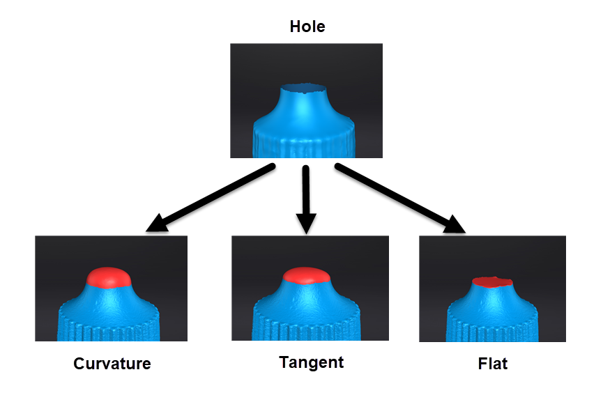 |
|
| Manual Hole Filling | After entering the manual hole filling mode, the hole edges are displayed green and get red after picking. The number of the holes and the number of holes filled will be displayed on the interface. Select filling types before picking a hole, including Curvature, Tangent or Flat, and then click the edges to perform filling actions. You can delete unwanted neighboring areas to delete edge noise data; the default value is 3, and the range is 0 ~ 10 (0 indicates no neighboring area deleted). |
|
| Optimization options | Description | Note |
|---|---|---|
| Flip Normal | To redefine the front direction of the scanned data in reversal design. Hold Shift+left mouse button to select areas to be flipped. |
|
| Cutting Plane Tool | Define a plane to re-adjust the coordinate system of the scanned data. Hold Shift+left mouse button to select a plane by drawing a straight line, switch the selection area through the Reverse Selection button and then activate Delete selection and close intersection or Delete selection. |
|
| Mirror | Take the front view plane of scan data as the working plane. Draw a straight line as the central axis and perform a symmetrical copy. Hold Shift+left mouse button to draw a straight line as the central axis and then the data will be reproduced axisymmetrically with this line; you can tick to Keep the initial mesh. |
|
| Optimization options | Description | Note |
|---|---|---|
| Zoom | Adjust the scaling ratio of the model, but it will not reduce the number of triangular slices and the size of the data. The default value is 100, indicating no zoom. |
|
Data Editing Toolbar

| Icon | Function | Description |
|---|---|---|
 |
Select through | To select data all through. |
 |
Select visible | To select data on the front view only. |
Note
For other editing functions, please refer to data editing.
Side Function Bar
| Icon | Function | |
|---|---|---|
 |
Open file | Open a file (STL, OBJ, PLY) for post processing. |
| Export the scan | ||
 |
Share your scan | Use your |
 |
Third-party software | Save the data and open with third-party software. |
| Model display | After enabling the model display by clicking the icon or pressing F12, the model will rotate at a specified speed (Click  Note NoteThe model will only rotate and display from the current view after entering the model display interface. Exit and adjust the angles in the post-processing interface if other views are in need. |
Context Menu
| Function | Description |
|---|---|
| Select Through | To select data all through. |
| Select Visible | To select visible data on the front view only. |
| Switching the Display Type | You can select different display types (triangles, wireframe, point cloud data as well as triangles and wireframes) and the data display mode of the 3D scene will change synchronously after switching.Note It is accessible after clicking Preview during meshing. |
For the introduction to other functions, please refer to data editing.
Shortcuts
Please refer to data editing.