Data editing
When you start scanning, you can edit the scanned data in the Scan Step to generate accurate point clouds. You can also use other functions.
Data Editing Toolbar
You can use following tools to edit the scanned data after the scanning is paused or the point cloud is generated.

Note
- After editing the data, you can continue scanning to acquire more data.
- If the necessary editing operations have been performed on the scan data, please
 apply the edits before generating the point cloud.
| Icon | Function | |
|---|---|---|
| Perspective View | The object appears larger when closer, and smaller when farther away, which is consistent with the rule of normal human eyes to observe the 3D world. You can click this button to switch to Orthogonal View. |
|
| Orthogonal View | The object does not appear larger when closer, and smaller when farther away; also known as "isometric view", the size of the object displayed in the view is independent of the current viewpoint distance. You can click this button to switch to Perspective View. |
|
 |
Multi View | 6 different view angles to choose. |
 |
Cutting Plane | Create a plane to do quick cut. |
 |
Edit Point Cloud | In this mode, the selection tool is used to only select point cloud data; by clicking this button, you can switch to Edit Markers mode or Edit Markers & Point Cloud mode (Edit Point Cloud mode is enabled by default if there is a point cloud).  Note Note
|
 |
Edit Markers | In this mode, the selection tool is used to only select markers data; by clicking this button, you can switch to Edit Point Cloud mode or Edit Markers & Point Cloud mode (Edit Point Cloud mode is enabled by default if there is a point cloud). Note
|
| Icon | Function | |
|---|---|---|
| Edit Markers & Point Cloud | In this mode, the selection tool is used to select both markers and point cloud data; by clicking this button, you can switch to Edit Point Cloud mode or Edit Markers mode (Edit Point Cloud mode is enabled by default if there is a point cloud)Note
|
|
 |
Rectangular | Select / Deselect a rectangular area. |
 |
Polygon | Select / Deselect a polygon area. |
 |
Lasso | Select / Deselect the area by using the Lasso tool. |
 |
Line | Hold down Shift and left mouse button (LMB) and move the cursor to draw a straight line to select/deselect the area. |
 |
Paint brush | Hold down Shift or Ctrl and a red circle will appear. At this time, roll the mouse wheel will zoom in and out of the circle. Move the red circle to select / deselect the area to be edited. |
| Icon | Function | |
|---|---|---|
 |
Select all | Select all of the data. |
 |
Unselect | Cancel all selected areas. |
 |
Connected domain | Click the button after selecting a patch of data and all connected region to the selected data will be picked. |
 |
Invert | Revert the selection. |
 |
Delete selected data | Click this button or Del to delete selected data. |
| Icon | Function | |
|---|---|---|
 |
Undo | Undo the last deletion and recover the last deleted data. Multiple deletions can be undone by clicking multiple times. |
| Redo | Redo the last deletion and recover the last operated data. Multiple deletions can be redone by clicking multiple times. |
|
 |
Cancel edit | Undo all edits, and exit the edit mode. |
|
Apply edit | Click the button or space bar to apply the edit, and exit the edit mode. |
Side Function Bar
You can use more functions in the right-side function bar in scanning.
| Icon | Function | |
|---|---|---|
| Global optimization | After completing scanning, optimize and generate the point cloud. | |
 |
Project group | Create / open a project group. |
 |
Align | Align the data. |
| Export the scan | ||
 |
Mesh | Will move to next step Post-processing to mesh model.Note This button is not available before the point cloud is generated. |
Context Menu
| Function | |
|---|---|
| Select all / Invert / Unselect / Delete selected data | Their function is the same as that of the corresponding buttons in the editing bar, and can be operated by shortcut keys. |
| Fitting View | The data on the interface is displayed in the center according to the appropriate size, and it can be operated by shortcut keys. |
| Sampling Display | For the project with a large volume of point clouds, the software will prompt you to sample and display the interface data in a pop-up window. You can also manually use this function to adjust the scale of data display. |
| Set Rotate Center | The rotation center can be set on the data by the left mouse button, press esc to exit, and it can be operated by shortcut keys. |
| Reset Rotate Center | After reset, the center of rotation is at the data center. |
| Show / Hide Cutting Plane | Click to hide or show the cutting plane (if has been set). |
Shortcut
| Shortcut | Function |
|---|---|
| Press and hold Ctrl+D | Fit view |
| Scroll wheel | Zoom in / out the model |
| Press and hold the Middle Button and move the cursor | Pan the model |
| Press and hold the Left Button and move the cursor | Rotate the model |
| Double click Left Button | Select data |
| Press and hold the Shift+Left Button | Select the area of data |
| Press and hold the Ctrl+Left Button | Deselect the area of data |
| Press and hold Ctrl+A | Select all |
| Press and hold Ctrl+C | Deselect all data |
| Press and hold Ctrl+I | Switch selected/unselected data |
| Del | Delete the selected data |
Cutting Plane
If you need to remove the object's base data during the scanning process, the Cutting Plane can be a very effective tool.
By setting up a cutting plane, the data below the plane will not be captured.
Note
After opening the global markers file or scanning the global markers (before or after optimization), it supports creating a cutting plane, and the global markers can be saved together optionally.
Create a cutting plane
The three methods for creating the cutting plane are shown below.
| Method | Description |
|---|---|
| Fitting Point Cloud | Press Shift+Left Button to select data, and then click Create Plane to generate the cutting plane. |
| Creating Straight Line | Press Shift+Left Button to draw a line, and then click Create Plane to generate the cutting plane. |
| Markers | Press Shift+Left Button to select at least 3 markers, and then click Create Plane to generate the cutting plane. |
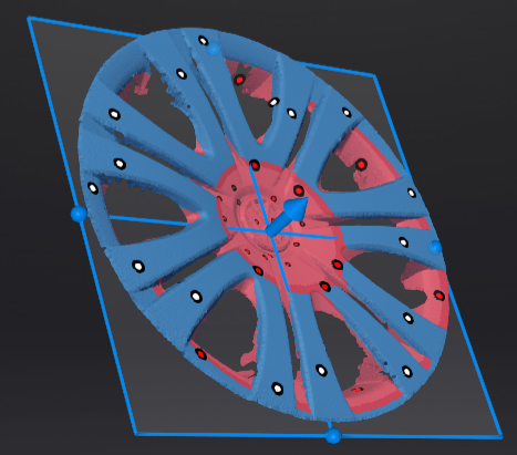
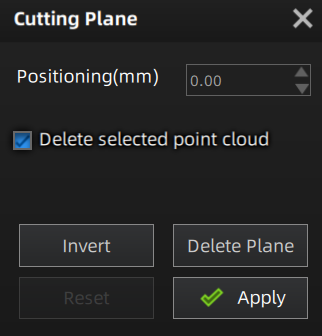
Set the Cutting Plane
Col
- Delete selected point cloud / markers: When ticked, the selected point cloud data or markers will be highlighted in red. Apply the edit to delete the highlighted point cloud data or markers.Note
- It is not supported to deleted all point cloud data. At least four markers should be remained at the front appearance of the cutting plane.
- If it is the auto cutting plane, only the selected markers can be retained, and the selected point cloud data is deleted by default.
- Invert: To reverse the selection of data by flipping the cutting plane.
- Delete Plane: To delete the current cutting plane and return to the interface for creating a new cutting plane.
- Reset: To reset all the operations performed after creating the cutting plane.
- Apply: To apply all edits.
Col
Col
- Pan the cutting plane: After generating the plane, you can enter numbers in the editing box or drag the arrow of the cutting plane's normal
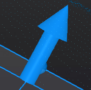 to pan the cutting plane.
 - Rotate the cutting plane: You can drag any of the four small balls on the edges of the cutting plane
 to rotate the cutting plane along a certain direction.
Col