Parameter Settings
After entering the Scan interface, you can set related parameters on the left side of the interface, including camera parameter settings and scan settings (such as resolution, align mode, monocular-stereo fusion, etc.). You can also set the turntable parameters in the turntable settings card on the right side of the interface.
Note
If you need to set turntable parameters, please connect the turntable first.
Camera Parameter Settings
Col
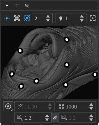
Preview the real-time image captured by the scanner's camera through the camera window, which can assist you in determining whether the camera brightness is appropriate. You can also make adjustments using camera parameters such as exposure, projector and gain.
Col
Note
- When you move the cursor over the camera window, you can zoom in and out on the video stream by scrolling the wheel up and down (not supported for the
 Automatic exposure mode).
 - When using the stepper, you can adjust the value by directly entering a number, clicking
 or scrolling the mouse wheel up and down (when moving the cursor over the input box).
Close the camera window |
The left camera window is displayed by default, and you can click this button to close the camera window; then you can click |
|
Dual Camera |
When disabled (default), it will display the left camera window; you can manually enable it to display the left and camera windows simultaneously. | If the |
Zoomed view |
When enabled, you can preview the scanning effect more intuitively and check the markers. | Only when the |
Laser projector |
When enabled, you can view the laser points |
|
Real-time recognition |
When enabled, you can view the number of recognized markers
|
|
Background cutting |
If the scanning background is cluttered, you can enable this function to automatically mask the background of the object to be scanned. Once enabled, a stepper will be displayed to adjust the background cutting value; the larger the value set, the greater the cutting range. | It is recommended that you enable the |
Optical autofocus |
If the optical cross projection is blurry or the scanning effect lacks clarity, you can use this function; but before using this function, please move the object to the appropriate position to ensure that the two laser points overlap (the |
After using this function, recalibration is required; otherwise, the monocular-stereo fusion function cannot be used. |
Projector |
If the object's material is highly reflective, it is recommended that you reduce the brightness of the projector, which is the brightness of the stripes projected by the scanner. | If the brightness of the projector is too high, it may cause issues such as overheating of the device. Please pay attention to the device temperature when adjusting the projector's brightness to extend the device's lifespan. |
Point cloud exposure |
If you need to adjust the brightness of the scanned point cloud, you can use the stepper to adjust the point cloud exposure level; the higher the level, the longer the exposure time, the higher the brightness. It supports adjusting the exposure mode as If the 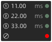 |
|
Marker exposure |
If you need to adjust the brightness of the scanned markers, you can use the stepper to adjust the marker point exposure level; the higher the level, the longer the exposure time, the higher the brightness, and the more marker points will be recognized (the |
If the exposure time is too long, it usually means that the scanning speed will be slower, resulting in longer scanning duration. |
Gain |
For objects of different colors and materials, you can use the stepper to adjust the camera gain to obtain better scanning data; it supports |
The greater the gain, the more noise there will be on the surface of the scanned object. |
Note
Grayscale uses black tones to represent objects, using black as the base color and different saturations of black to display the image. Each grayscale object has a brightness value ranging from 0% (white) to 100% (black). Images generated by black-and-white or grayscale scanners are typically displayed in grayscale.
Scan Setting
Resolution
You can set the sampling resolution for scanning: Low, Med, and High (default); for projects with a large amount of scanning data and lower precision requirements, the resolution can be appropriately lowered.
Note
- Multiple scanning data with different resolutions can coexist within a single project.
- Before starting a scan and after pausing a scan, it is possible to switch the resolution, and the scanning will be sampled according to the latest parameters.
- In addition to lowering the sampling resolution, you can also manually adjust the display resolution.
Align Mode
| Align Mode | |
|---|---|
| Markers | It is suitable for objects with fewer features or symmetrical features, as well as objects requiring high scanning accuracy. It requires placing markers on the surface of the object. Note NoteAfter completing the scan, you can save the markers file (.p3 / .dgm / .asc). |
| Features | Automatically complete the alignment by the surface geometric features of the object to be scanned. This mode is used for objects that cannot place markers and have rich surface features.Note In this mode, markers can not be recognized. |
| Hybrid Alignment | Mixed markers and features align modes. |
| Global Markers | It is suitable for objects with fewer features or symmetrical features, as well as objects requiring high scanning accuracy. It requires placing markers on the surface of the object, and it supports After switching to scan point cloud, you can tick Add global markers to automatically add the recognized global markers during the scanning process. Note
 Caution CautionThe scanning method cannot be switched to scan global markers after scanning the point cloud data. If you need to scan global markers, please use the global markers mode first. |
| Turntable Alignment | It is suitable for objects with rich surface features. After the turntable is connected, the turntable steps, speed, and turns can be set. |
Caution
- In the Markers align mode, during the scanning process, if a few markers are placed on the turntable or the object being scanned, and the scanned object needs to be moved, please note the following points:
- When scanning different sides of the object, please create corresponding projects for each side, ensuring that the common area between different sides has more than 4 markers in common.
- After scanning, please clean up the miscellaneous data and retain all scanned markers.
- After scanning is complete, select the Manual Markers Alignment to align.
- In the global markers align mode, each project supports only one align mode and cannot be used simultaneously with other align modes.
- In the Hybrid and Features align modes, the turntable is not allowed to use.
- Both the Markers and Global Markers align mode support connecting the turntable.
- If markers have been placed but no data can be collected, please check the condition of the placed markers (there should be at least 4 markers within each scanning area, and at least 4 common markers between adjacent scanning areas) or switch the align mode.
Scan Target
Please choose the appropriate scanning target based on the actual material or color type of the scanned object:
 : Normal object.
 : Black / Reflective object.
Monocular-Stereo Fusion
For scanning objects with deep holes or recesses, it is recommended that you enable the monocular-stereo fusion function, which will retain more scanning data, specifically all data scanned by the left and right cameras.
Note
- If this function is disabled, only the common data scanned by the left and right cameras will be retained.
- This function can be set only while the device is connected before or after scanning.
- If the scanning mode is switched or the
 optical autofocus function has been used, the recalibration of the current scanning mode is required before using this function.
Caution
If data layering occurs during scanning, it is recommended that you perform recalibration before enabling this function.
Auto Cutting Plane
When enabled (default), a cutting plane will be automatically created based on the markers on the plane during scanning; after creation, editing the cutting plane is supported.
Note
- This function is only supported for Markers / Hybrid / Global Markers modes.
- Please enable this function before starting the scan; if there are already point cloud or markers data in the current project, the automatic creation process will not be initiated.
- If the scanning project does not recognize a suitable plane (containing 4 or more markers), the automatic creation process will not be initiated.
- If a turntable is currently being used, it is recommended that you evenly place markers on the turntable surface and avoid placing markers in a regular pattern to ensure the normal functioning of the turntable.
- After the cutting plane is automatically created, only the option to delete the selected markers is supported, with the default setting being to delete the selected point cloud.
Scan Box
When enabled (default), the field of view of the scanner's head will be displayed in real-time as a 3D translucent cone during each stage of scanning, assisting in checking the integrity of the scanning data.
Note
- When the device is offline, the 3D field of view is not displayed.
- When using shortcut keys to rotate, pan, or using
 Zoom to Fit function, the field of view will also change synchronously.
 - In the Markers / Global Markers align mode, the recognized markers will be displayed in real-time within the field of view.
Single Frame Completeness
Higher completeness may increase noise, but it is recommended when deep holes or sharp corners are present.
Marker Size
When the real-time recognition function is enabled, you can ![]() check the marker's size you need to recognize (1 mm, 2 mm or 4 mm), and the corresponding markers will be displayed in the camera window according to the selected size.
check the marker's size you need to recognize (1 mm, 2 mm or 4 mm), and the corresponding markers will be displayed in the camera window according to the selected size.
Note
Only the Markers / Global markers alignment supports the recognition of the specified size markers.
Turntable Settings
When the turntable is enabled, the connected turntable can be used for scanning.
Caution
- Before using the turntable, please select an align mode first; after the turntable completes one full rotation, the align mode can be reselected.
- If markers have been places but no data can be collected, please check the condition of the placed markers (there should be at least 4 markers within each scanning area, and at least 4 common markers between adjacent scanning areas) or switch the align mode.
Col
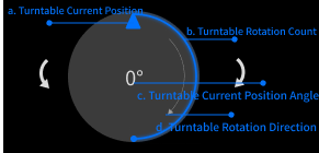
Turntable display panel:
Long press ![]() /
/ ![]() or input the value of Rotation Angle to adjust the starting position of the turntable rotation; other display rules are shown in the right image and can be updated by adjusting the parameters on the control panel.
or input the value of Rotation Angle to adjust the starting position of the turntable rotation; other display rules are shown in the right image and can be updated by adjusting the parameters on the control panel.
Col
Col
Turntable control panel:
- Rotation Angle: Set the rotation angle of the turntable from - 360° to 360°.
- Turntable Settings: Set the number of rotations for the turntable to one turn or half turn. You can also customize the rotation direction as
 counterclockwise or
  clockwise (default) and set a custom rotation angle (1° ~ 360°).
 - Turntable Speed: Set the speed (1 ~ 12), with a default value of 12.
-
Steps: Set the number of scans for one turn of the turntable (2 ~ 180), with a default value of 8.
-
Use existed verify data: When enabled, the existing axis data will be used for alignment directly, or the recalibration is required before scanning and alignment.
Caution
Please enable this function only when the object to be scanned or the turntable has not been moved; otherwise, please disable it and recalibrate the turntable data.
Col
