Interface
Click ![]() for the Scan step in the top navigation bar to enter the scan interface.
for the Scan step in the top navigation bar to enter the scan interface.
Note
If there is currently no project group, please select New project group or Open project group.
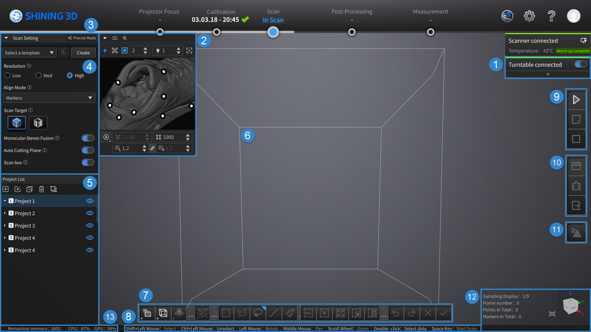
Interface Overview
Note
For the details of the top navigation bar, the button in the upper right corner and the device status card, please refer to software interface.
① Turntable Settings Card
Col

Turntable not connected
Col

Turntable connected
Note
- If the turntable is connected, the turntable function is enabled by default and can be manually disabled; if the turntable is not connected, the turntable function cannot be enabled.
- The turntable panel is expanded by default, and you can click
 to collapse it; then you can click
  to expand it.
 - For more introduction to the turntable settings, please refer to turntable.
② Camera Window
View the actual scene during the scanning process through the left (default) and right camera windows to facilitate accurate camera parameter adjustment.
Note
- After moving the cursor to the camera window, you can zoom in and out of the video stream by scrolling the mouse wheel up and down.
- If the
 Laser projection function is enabled, you will see the laser points
  on the scanned object, then you can determine if the distance is appropriate by checking whether the two projected laser points overlap.
 - If the
 Real-time recognition function is enabled, you can view the recognized markers
  in the camera window.
③ Scanning Mode and Template
Display the ![]() scanning mode (precise mode / wide mode) of the current scanning project.
scanning mode (precise mode / wide mode) of the current scanning project.
Note
Please select the scanning mode when creating a new project group, as it cannot be modified once you enter the scanning process. Besides, when creating a single project within the current project group, you can switch the scanning mode.
You can set the scanning template, including camera parameter settings and other scanning settings:
- To use a new template: Click Create to create a template with the current parameter settings. The first template will have the default name "DefaultTemplate_01." If you modify the parameter settings after creation, the software will prompt "The template has been modified, please keep it up to date", and you can click
 to update the template.
 - To use an existing template: Click
 to expand the template dropdown list and select an existing scanning template (support Update the template). Additionally, you can click Open Local File to open the software root directory, where you can rename or delete templates and perform other operations.
Note
- The scanning template format is *.templ_q.
- Please use a scanning template with the correct file version, and ensure that the selected scanning template matches the current device type and scanning mode.
- If a scanning template is used in the Scan step, it can continue to be used and updated in the Post-Processing step; otherwise, the template module will not be displayed in the Post-Processing step.
④ Scanning Settings
To set scanning parameters such as resolution, align mode, monocular-stereo fusion and so on, please refer to scan settings.
⑤ Project List
Display all projects in the current project group. For more introduction to the operation buttons, please refer to project.
⑥ 3D Scene
View the scanning effect and Scan box (if available).
Note
It is recommended that you enable the Scan box function, which will display the recognized field of view of the scanner's head in real-time, helping to assess the completeness of the scanning data.
⑦ Edit Toolbar
Edit the scan data of the model and adjust the viewing angle. Please refer to data editing for specific instructions.
⑧ Shortcut
Adjust the angle of models, move models and select data quickly. Please refer to shortcuts for specific instructions.
⑨ Scanning and Global Optimization
Start / Pause scanning, delete the scanned data and perform global optimization. Please refer to scanning for specific instructions.
⑩ Right-side Function Bar
Import the project, alignment, delete and save data. Please refer to the right panel for specific instructions.
⑪ Mesh Model
Convert point cloud data into triangular mesh data. Please refer to mesh model for specific instructions.
⑫ Other Information
Display the total triangles and points of the current project.
Click ![]() fitting view button can automatically adjust the size of the model view to fit the screen size.
fitting view button can automatically adjust the size of the model view to fit the screen size.
Col
Click ![]() fitting view button can automatically adjust the size of the model view to fit the screen size. In addition, a view controller is provided in the lower right corner for easy switching of perspectives, as shown in the right figure.
fitting view button can automatically adjust the size of the model view to fit the screen size. In addition, a view controller is provided in the lower right corner for easy switching of perspectives, as shown in the right figure.
Col
⑬ Remaining Memory / CPU / GPU
- Remaining memory: The percentage of remaining memory space.
- CPU: The amount of computer CPU resources being utilized by this software program.
- GPU: Graphics card usage rate.
Note
If the program is utilizing an excessively high percentage of resources, it is recommended that you close non-scanner software and wait patiently.