Alignments
Support  best fit alignment,
  transform alignment,
  manual alignment and
  align to coordinate system.
Note
For a measured model, multiple alignment methods can be used to calculate multiple alignment results. However, in the current model preview scene, only one alignment result can be displayed (right-click and Activate the alignment object in the left-side tree view) to determine the current pose of the measured model. Active alignment objects can be deleted by right-clicking on them.
Best Fit Alignment
Through the best fit alignment, you can align the measured model automatically by moving its pose based on the reference model, minimizing the overall average distance deviation.
Note
Before using the best fit alignment function, please import the reference model and the measured model.
Advanced Settings
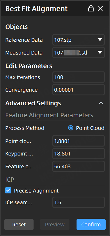
- Point Cloud Sampling Radius: The uniform sampling radius of the point cloud before alignment. The smaller this value is set, the higher the sampling density, which may lead to a higher alignment success rate, but with lower efficiency.
- Keypoint Sampling Radius: The smaller this value is set, the higher the alignment success rate, but with lower efficiency.
- Feature Calculation Radius: After sampling key points, features are calculated within the feature calculation radius centered on each key point.
- ICP Search Radius: After feature alignment, the initial poses of the two models are relatively close, requiring fine-tuning through ICP alignment. This fine-tuning involves multiple iterations, and the range searched from one model to the surrounding area during each iteration is the ICP search radius.
Operation Steps
The steps for performing the best fit alignment are as follows:
Col
- Click Best Fit Alignment to open the corresponding window.
-
Select the reference data and measured data to be aligned, and edit the parameters (sampling rate1, maximum iterations2 and convergence3).
Note
Expand Advanced Settings and set Feature Alignment Parameters and ICP to improve alignment accuracy.
-
Click Preview to preview the alignment result in the 3D scene; then click Apply to save the alignment object, which will be displayed in the align group corresponding to the measured model in the left-side tree view.
Col
Transform Alignment
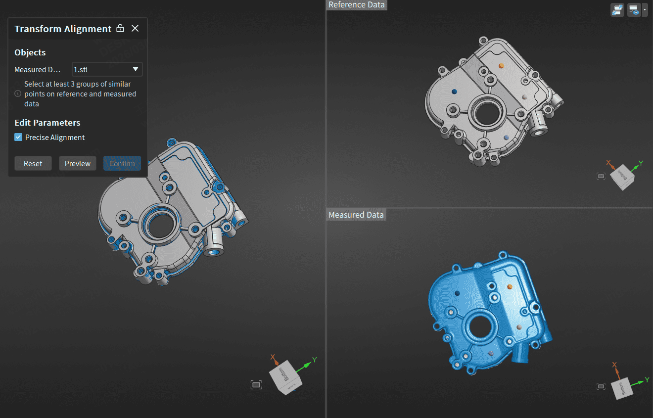
In cases where the best fit alignment function cannot be used for automatic model alignment, you can use the transformation alignment function to manually align the reference and measured models by selecting at least three (up to six) sets of points on them.
Note
Before using the transform alignment function, please import the reference model and the measured model.
The steps for performing the transform alignment are as follows:
- In the Alignment Tools bar, click Transform Alignment to open the corresponding window.
- Select the measured data for alignment and choose at least three (up to six) sets of points on models in the Reference Data and Measured Data windows respectively:
- Drag the points to change their positions.
- Right-click on a point to change the tag color of that point.
- Press Del to remove a selected point.
- Click Preview to preview the alignment result in the 3D scene; then click Apply to save the alignment object, which will be displayed in the align group corresponding to the measured model in the left-side tree view.
Manual Alignment
In cases where there are noticeable differences between the pose of the measured model and the reference model, manual alignment can be used to make fine adjustments to the initial position of the measured model.
Note
Before using the manual alignment function, please import the measured model.
The steps for performing the manual alignment are as follows:
Col
- Click Manual Alignment to open the corresponding window.
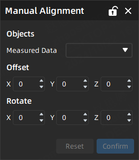
- Select the measured data to be aligned, and edit the pan distance or rotation angle of the model on the X / Y / Z axes; you can also manually drag or rotate the movable coordinate axes at the center of the model in the 3D scene.
- Click Confirm to save the alignment object, which will be displayed in the align group corresponding to the measured model in the left-side tree view.
Col
Align to Coordinate System
If you only need to measure the measured model, you can first align the measurement model by adjusting its orientation to match the predefined global coordinate system. This will facilitate better observation and measurement of the model in subsequent steps.
This method involves aligning the model by determining six degrees of freedom, primarily used for measuring gauge models.
Note
- Before using the 3-2-1 alignment function, please import the measured model.
- If you select an existing circle or sphere feature, the corresponding center of the circle or sphere will be taken as the reference point; if you select an existing cylinder or cone feature, the corresponding axis of the cylinder of cone will be taken as the reference line.
The steps for performing aligning to coordinate system are as follows:
Col
- Click Align to Coordinate System to open the corresponding window.
-
Select the measured data to be aligned, and choose the method:
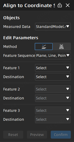
 Plane, Axis, Center Point Alignment: Select the feature sequence, and select the features and their destinations based on the selected sequence one by one.
 Vertical Plane: Select the features and their destinations one by one.
-
Click Preview to preview the alignment result in the 3D scene; then click Confirm to save the alignment object, which will be displayed in the align group corresponding to the measured model in the left-side tree view.
Col
Note
- Plane, Axis, Center Point Alignment:
- Please select at least one created plane, line or point feature, and the corresponding destination.
- Please select the corresponding features based on the selected sequence; otherwise, it will prompt "
 This feature type is not supported".
 - If you reselect the feature sequence, all selected features and destinations will be cleared.
- If the feature 2 or feature 3 has been selected and you adjust feature 1 to "None", the other selected features will be automatically cleared. Similarly, if the destination for feature 2 or feature 3 has been selected and you set the destination for feature 1 to "None", the other selected destinations will also be automatically cleared.
- Vertical Plane:
- Please select at least one created plane and the corresponding destination.
- If the feature 2 or feature 3 has been selected and you adjust feature 1 to "None", the other selected features will be automatically cleared. Similarly, if the destination for feature 2 or feature 3 has been selected and you set the destination for feature 1 to "None", the other selected destinations will also be automatically cleared.
-
In point cloud or mesh data, the sampling rate refers to the number of data points collected per unit area or unit length (e.g., point spacing or point density). ↩
-
By setting the maximum number of iterations, the algorithm (such as the Iterative Closest Point (ICP) algorithm) is limited in its maximum number of repetitions to prevent infinite looping due to non-convergence, which is used to optimize fitting or alignment results; if the algorithm converges (meets the convergence target) before reaching the maximum number of iterations, it will terminate early. ↩
-
The convergence target value refers to the precision threshold at which the algorithm stops iterating, usually judged by the change or absolute value of the residual (e.g., Root Mean Square Error, RMS); when the error change between two iterations is less than the target value, the algorithm is considered to have converged. ↩