Measurement
You can measure on the model you just scanned, or you can open a model file to do the measurement, the software supports .stl, .obj, .ply files.
Create features
To use 3-2-1 System Movement, you need to create features first. There are three kinds of features you can create: point, line and plane.
Point
Two methods to create a point: Selected Points, Line-Plane Intersection. You can select different method from drop-down menu.
| Creation Method | Requirement | Description |
|---|---|---|
| Selected Points | - | 1, click on the data to select a point. 2, click Create to create a point. 3, repeat 1 and 2 to create more points. |
| Line-Plane Intersection | - line and Plane should be created in advanced. - line should not be parallel to the plane. |
1, click on the created line, or select it on the drop-down. 2, click on the created plane, or select it on the drop-down. 3, the point generated is the intersection between the non-parallel line and plane. |
Line
Two methods to create a line: Point-Point, Plane-Plane Intersection.
| Creation Method | Requirement | Description |
|---|---|---|
| Point-Point | need 2 points | 1, click on the model to create a point, or select a created point as the line starting point. 2, click or select another point as the line ending point. 3, click Create to create the line. |
| Plane-Plane Intersection | - 2 planes should be created in advanced. - planes should not be parallel. |
1, click on the plane previously created, or select it from the drop-down menu. 2, repeat for the second plane. 3, The created line is the intersection between the 2 non-parallel planes. |
Plane
Three methods to create a plane: 3 Points Fit, Point-Line Fit, Best Fit.
| Creation Method | Requirement | Description |
|---|---|---|
| 3 Points Fit | 3 points are not collinear. | 1, click on the model to create a point, or select a created point from drop-down menu. 2, repeat to create two other points. 3, click Create to create a plane. |
| Point-Line Fit | - line should be created in advanced. - point should not lie on the line. |
1, select a line created. 2, create or select a point. 3, click Create to create the plane. |
| Best Fit | - | 1, press Shift + LMB to select an area, press ctrl + LMB to deselect. 2, click Create to create the plane best fit for the area which you just selected. |
Movement
Use this mode to modify the alignment of the data to the global coordinate. This action is useful for post processing or reverse engineering.
The transformations do not affect the shape and size.
| Movement method | Description | Steps |
|---|---|---|
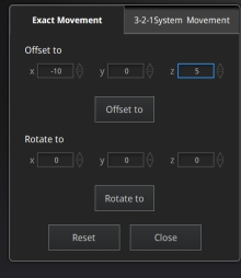
| Exact Movement | - Offset: adjust the object data center coordinates in X, Y, Z axis. - Rotation: adjust the rotation angle in X, Y, and Z axis. |
1. Enter the setting value then click Offset or Rotate. 2. Repeat step 1 until it meets your needs. 3. Click Close to save the results and exit. 4. Click Reset to cancel all movement. |
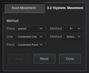
| 3-2-1 System Movement | 3-2-1 system movement aligns model by selecting the point, line and plane. Before movement, create feature points, lines and planes. The feature lines created are not perpendicular to the plane. The coordinate system on the interface represents the global coordinate system. Red=X+, Green=Y+, Blue=Z+. |
1. Make a one-to-one correspondence between the created feature points, lines and planes with the origin and axis of the coordinate system to be aligned. That is, the normal of the selected plane corresponds to the coordinate axis; the selected feature point corresponds to the origin. - Select a feature plane in the plane drop-down menu, and select an axis in the corresponding constraint drop-down menu of the plane. The arrow on the plane corner indicates the positive direction of the plane, and the selected axis direction will be consistent with the plane direction. - Select a feature line in the drop-down menu of the line, and select an axis in the drop-down menu of the line. The arrow of the line indicates the positive direction of the line, and the direction of the selected axis will be consistent with the direction of the projection of the line on the selected plane. -Click the drop-down menu to select a point, the position of this point is the origin of the coordinates (0, 0, 0). |
Measure
Three kind of measurements can be done in the software: Distance, Surface area and Volume.
| Measurement | Description | Steps |
|---|---|---|
| Distance | Calculates the distance between two points on the surface of the model. | Click on the surface of the model to pick two points, the calculation will be done automatically. - Total is the 3D distance, X, Y and Z are the projection of the segment to the respective planes. |
| Surface area | Calculate the surface area value. | - Press Shift + LMB to select an area, press Ctrl + LMB to unselect. - Ctrl + A to select all. - Click Calculate to display the Area value of the selected data in mm². |
| Volume | Calculate the volume contains in a watertight mesh. | It returns the volume in mm³ and the coordinates of the bounding box. - Only available for watertight mesh. |