Data Editing
To edit the scanned data when you pause or finish scanning.
Edit Toolbar
When you pause or finish the scanning, you can use the following tools to edit the scanned data.

| Icon | Function | Instruction |
|---|---|---|
| Perspective View | The object appears larger when closer, and smaller when farther away, which is consistent with the rule of normal human eyes to observe the 3D world. You can click this button to switch to orthogonal view. | |
| Orthogonal View | The object does not appear larger when closer, and smaller when farther away; Also known as "isometric view", the size of the object displayed in the view is independent of the current viewpoint distance; You can click this button to switch to perspective view. | |
 |
Multi View | 6 different view angles to choose. |
 |
Cutting Plane | Create a plane to do quick cut. For more, see Cutting plane. |
| Icon | Function | Instruction |
|---|---|---|
 |
Point Cloud Edit (IR Mode) |
Edit the selected data area in the point cloud edit mode. |
| Data Editing | Edit the selected data. Click |
|
 |
Edit Markers | Select the data area and the markers in this area will be shown in red. The red markers can be edited at this time. |
| Icon | Function | Description |
|---|---|---|
 |
Select Visible | To select data on the front view only. |
 |
Select Through | The surface data and the interior data can be selected at the same time. |
| Icon | Function | Instruction |
|---|---|---|
 |
Rectangular | Select / Deselect a rectangular area. The selected area is displayed in red. |
 |
Polygon | Select / Deselect a polygon area. |
 |
Lasso | Select / Deselect the area bu using the Lasso tool. |
 |
Straight Line | Hold down Shift+Left Button and move the cursor to draw a straight line to select/deselect the area. |
 |
Brush | Hold down Shift+Left Button and a red circle will appear. At this time, roll the mouse wheel will zoom in and out of the circle. Move the red circle to select/deselect the area to be edited. |
 |
Select All | Select all the data. |
 |
Unselect | Cancel all selected areas. |
 |
Connected Domain | Click the button after selecting a patch of data and all connected region to the selected data will be picked. |
 |
Invert | Revert the selection. |
 |
Delete Selected Data | Delete selected data. |
 |
Undo | The last deletion will be undone. You can click multiple times to undo multiple deleted data. |
| Redo | Redo the previous action. You can click multiple times to redo multiple actions. | |
 |
Cancel Edit | Undo all edits, and exit the edit mode. |
 |
Apply Edit | Click the button or space bar to apply the edit, and exit the edit mode. |
Caution
Once the edit has been applied, the original state cannot be restored, but only by reloading the file.
Shortcut
| Shortcut | Function |
|---|---|
| Press and hold the Left Button and move the cursor | Rotate the data |
| Press and hold the Middle Button and move the cursor | Translate the data |
| Hold down Shift+Left Button | Select the area of data |
| Hold down Ctrl+Left Button | Deselect the area of data |
| Scroll Wheel | Zoom in / Zoom out the data |
| Space | Apply the edit |
| Del | Delete the selected data |
Menu of the Right Mouse Button
| Function | |
|---|---|
| Select All / Invert / Unselect / Delete Selected Data | The function is the same as the function on editing bar, and can be operated by shortcut keys. |
| Fitting View | The data on the interface is displayed in the center according to the appropriate size. |
| Connected Domain / Select Through / Select Visible | For more, see Edit scanned data. |
| Switching the Display Type | You can select different display types(triangles, wireframe, point cloud data as well as triangles and wireframes) and the data display mode of the 3D scene will change synchronously after switching. |
| Set Rotate Center | The rotation center can be set on the data by the left mouse button. |
| Reset Rotate Center | After reset, the center of rotation is at the data center. |
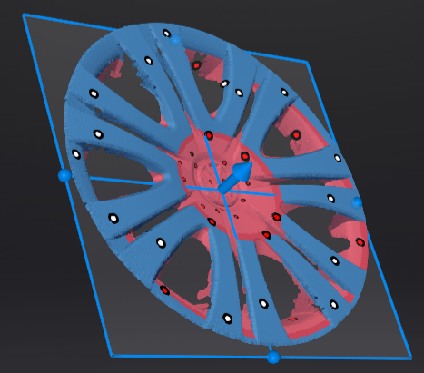
Cutting Plane
Remove the base data from the whole scanned data by creating a cutting plane.
Creation
-
Click
 .
. -
Select the creation method and follow the interface prompts to create the cutting plane.
| Method | Instruction |
|---|---|
| Scan Data Fitting | Press Shift+Left Button to select data, and then click Generate Plane. The direction of the plane will be calculated by the software according to the direction of the data. |
| Creating Straight Line | Press Shift+Left Button to draw a line, and generate the cutting plane according to the line. |
| By Markers | Press Shift+Left Button to select markers. 3 markers or more are required to generate the cutting plane. |
3.Click Create Plane.
Settings
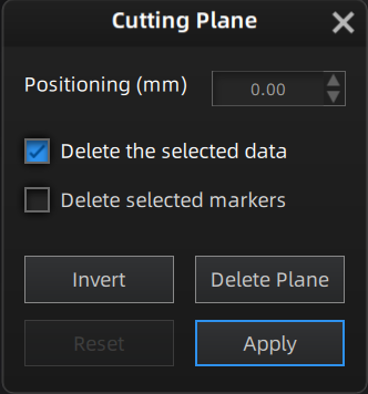  |
|
 to translate the cutting plane.
 .
.