Data Editing
A variety of tools are provided to process the 3D data. Users can use these tools to reduce image noises and obtain accurate 3D data.
Bottom Panel
After pausing or completing the scanning, you can use the following tools to edit the data.

| Icon | Function | |
|---|---|---|
| ! |
Perspective View | The object appears larger when closer, and smaller when farther away, which is consistent with the rule of normal human eyes to observe the 3D world. Click this button again to switch to Orthogonal View. |
| Orthogonal View | The object does not appear larger when closer, and smaller when farther away; the size of the object displayed in the view is independent of the current viewpoint distance; Click this button again to switch to Perspective View. |
|
| Multi view | Observe the data from 6 different views. | |
| Cutting plane | Create a cutting plane to make a quick cut. See more details in Cutting Plane. |
| Icon | Function | |
|---|---|---|
| Data editing | In this mode, only mesh can be chosen. Click it again to switch to Edit Markers. | |
 |
Edit markers | In this mode, only markers can be chosen. Click it again to switch to Data Editing. Note Note |
| Icon | Function | |
|---|---|---|
 |
Select visible | Select the outer data. |
 |
Select through | Select the inner and outer data. |
| Select Front | To select only the data on the front surface of the current object.Note |
| Icon | Function | |
|---|---|---|
| Rectangular | Select or deselect a rectangular area. |
|
| Polygon | Select or deselect a polygon area. |
|
| Lasso | Select or deselect the area by using the lasso tool. |
|
 |
Line | Select or deselect the area by using the straight line tool. |
| Paint brush | Select or deselect the area by using the brush tool. |
| Icon | Function | |
|---|---|---|
| Select all | Select all of the data. | |
| Unselect | Cancel all selections. | |
| Connected domain | Click the button after selecting a patch of data and all connected region to the selected data will be selected. | |
| Invert | Revert the selection. | |
| Delete Selected Data | Click it or press Delete to delete the selected data. |
| Icon | Function | |
|---|---|---|
| Undo | The last operation will be undone. Click multiple times to undo multiple operations. | |
| Redo | The last operation will be redone. Click multiple times to redo multiple operations. |
|
| Cancel edit | Undo all edits. | |
| Apply edit | Apply all edits. |
Caution
Once the edits are applied, the data can not be recovered only if you re-load the file.
Right Panel
| Icon | Function | |
|---|---|---|
| Preview / Scan / Pause | To preview the scanned data / To start scan / To stop scan. | |
| Global markers optimization | To optimize the global markers. | |
| Project group | To create / open a project group. About the project group, please refer to Project Settings. |
|
| Delete your scan | To clean the current data to redo scan. | |
| Alignment | To align the data as you need, please refer to Alignment. | |
| Export the Scan | ||
| Mesh optimization | To do mesh optimization and mesh processing. Note |
|
| Mesh processing | To do mesh processing. Note This function is recommended if you scan the mesh with scanning global markers first. |
Keyboard Shortcuts
| Shortcut | Function |
|---|---|
| Hold down Left Button and move the cursor | To rotate the data |
| Hold down wheel button and move the cursor | To move the data |
| Shift + Left Button | To select an area |
| Ctrl + Left Button | To cancel the selection |
| Middle Button | To zoom in / out the data |
| Space | To apply all edits |
| Delete | To delete the selected data |
Context Menu
| Function | |
|---|---|
| Select all / Invert / Unselect / Delete selected data | The same as edit tools. You can use these functions by shortcuts. |
| Fitting view | To display the data at the center appropriately. |
| Connected domain / Select through / Select visible | The same as editing tools. |
| Switching the display type | To display the data in point, line, plane and line-plane. |
| Set rotate center | The rotation center can be set on the data by the left mouse button. |
| Reset rotate center | After reset, the center of rotation is at the data center. |
Cutting Plane
Remove the base data from the whole scanned data by creating a cutting plane.
Creation
-
Click
 .
. -
Select the creation method and follow the interface prompts to create a cutting plane.
Method Instruction Scan data fitting The plane that the selected data are in will be the cutting plane. Creating straight line The plane that the straight line cuts through will be the cutting plane. Markers The plane that the markers (at least three) are in will be the cutting plane. -
Click Create Plane.
Setting
| Illustration | |
|---|---|
 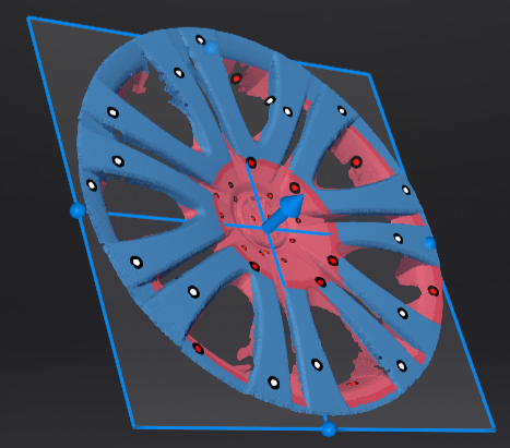 |
|
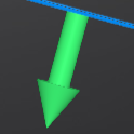 to translate the cutting plane.
 .
.