Cross-Section Creation
You can use sectional tools to create  cross-sections.
After creating cross-sections, you can extract measured cross-sections, or create features from cross-sections.
Note
- Before using the cross-section function, please import the reference model or measured model.
- After entering the From Cross-Section function or hiding the model, you can view the cross-section view.
- The cross-section function window is locked by default, shown as
 . Click again to unlock the window.
Creation Steps
-
In the Sectional Tools bar, click
Cross-Section to open the corresponding window. -
Select the model to create cross-sections and edit parameters:
-
Creation method is From Plane: Select an already created face feature as the plane, and set the offset distance.
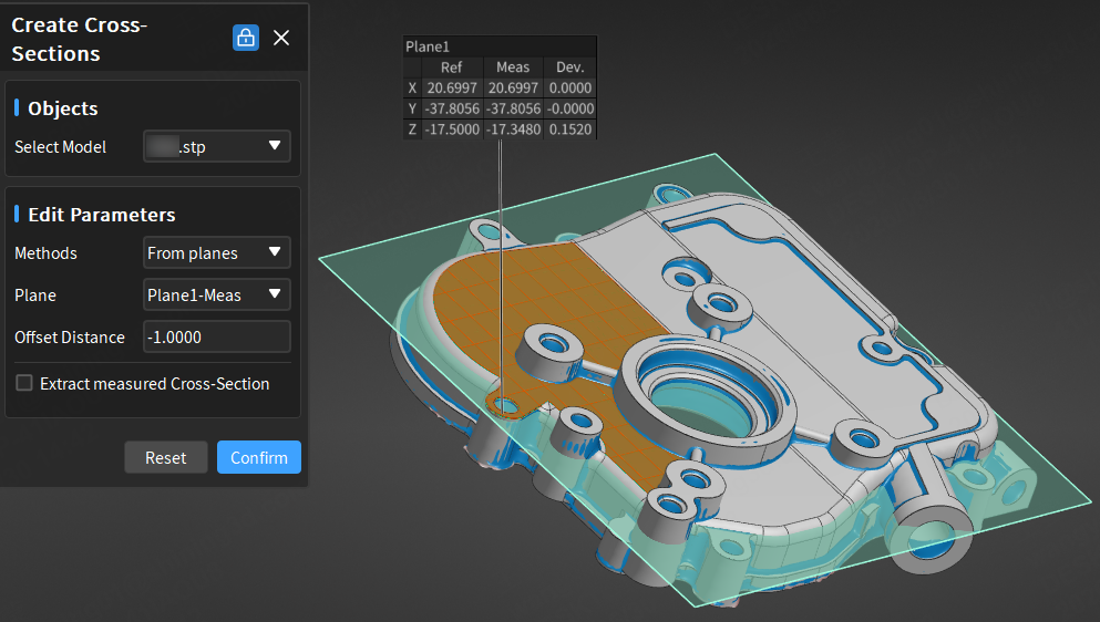
-
Creation method is Along Specified Direction: After selecting a direction (X-axis / Y-axis / Z-axis / Custom), you can click a point on the model in the 3D scene or enter the center point coordinates to create.
Note
- Modify the center point coordinates to adjust the cross-section to be created before clicking Confirm.
- In addition to X-axis / Y-axis / Z-axis / Custom directions, you can also select created axis-type features (line reference features, line measured features, cylinder reference features, cylinder measured features, cone reference features, cone measured features) as the creation direction.
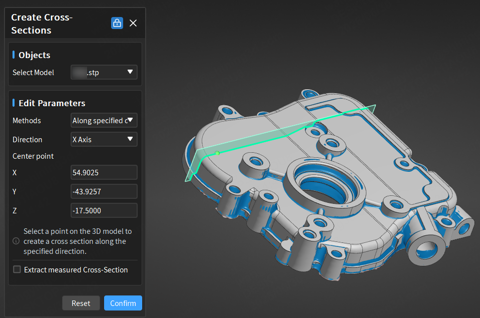
-
-
After completing relevant settings, you can preview this plane on the model in the 3D scene; then click Confirm to create this new cross-section, and it will be displayed in the
 cross-section module of the left tree view as
  cross-section reference object or
  cross-section measurement object.
Note
- If a measured feature is subsequently deleted, it will affect the cross-section measured features created from it.
- If the entered offset distance or center point coordinates deviate significantly from the current model and the preview cross-section does not intersect with the model, clicking Confirm will result in creation failure.
Extract Measured Values
If the created cross-section is a reference cross-section, you can extract the corresponding measured cross-section through automatic or manual methods.
- Automatic Extraction of Measured Values: In the upper right corner
 Settings > Calculation of the software interface, enable Automatic Extraction of Measured Values, or check
  Extract Measured Cross-Section in the creation window. The software will automatically extract the corresponding measured cross-section with default parameters after creating any reference cross-section.
 - Manual Extraction of Measured Values: After creating a reference cross-section, right-click the
 cross-section group in the left tree view, select Extract Measured Cross-Section and specify the measurement model to be extracted; you can specify Alignment Object in the Extract Cross-Section pop-up window.