Data Editing
When the scan is paused and there is point cloud or mesh data, you can tap ![]() to enter the data editing interface.
to enter the data editing interface.
-

Use touch gestures to rotate/zoom/pan the model. -

Use the lasso tool to select a specified area, supporting touch gestures to zoom the model. -
 /
/  /
/  Mesh/Point Cloud/Markers
Switch between mesh, point cloud, and marker data. -
 Expand / Connected Domain
Select all data connected to the currently selected area. -
 Invert Selection
Select all currently unselected data. -
 Deselect All
Deselect all currently selected data. -
 Undo
Undo
Undo the most recent deletion operation and restore the deleted data. -
 Revert
Restore to the state before the last edit. -
 Delete
Delete the selected data. (You can choose whether to retain the markers.)
Caution
Deleting all the markers is not supported. To ensure the alignment is completed, at least 4 markers must be retained.
 Cutting Plane
Manual Creation
When the scan is paused and there is point cloud, mesh, or marker data, you can create a cutting plane. Data below the cutting plane will not be collected and can be used to remove the base data of the object.
-
Select mesh, point cloud, or marker data; if there is only a single data type, no selection is needed.
- : Mesh
- : Point Cloud
- : Markers
-
Slide to draw a closed shape. The area within the lasso will be selected.
Note
- Zooming the model is supported. Tap to also pan and rotate the model. For gesture instruction, refer to Touch Gesture.
- If selecting markers, the area must contain at least 3 markers.
- Unselected marker:

- Selected marker:

- Unselected marker:
- Zooming the model is supported. Tap
-
Tap Create. The normal vector of the created cutting plane will be blue on the front side and red on the opposite side.
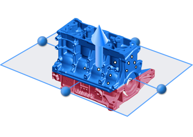
-
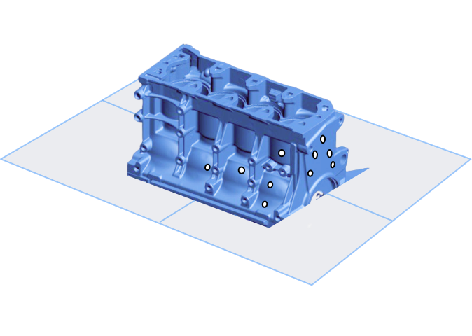
Tap Apply to delete the data in the red area below the cutting plane (marker data remains intact). You will return to the scan paused interface.
Automatic Creation
During scanning, the system automatically recognizes and creates cutting planes based on coded targets.
-
Place coded targets on the surface where you want to create a cutting plane.
-
The software automatically identifies these coded targets and generates the corresponding cutting plane.
Caution
- If a cutting plane already exists, the system cannot recognize additional coded targets to create new cutting planes.
- Once created, moving or removing the coded targets does not affect the existing cutting plane.
- Automatic cutting plane creation is not available in Infrared mode, Local Resolution mode, or AI Feature Recognition mode.
Editing Cutting Plane
| Operation | Steps |
|---|---|
| Move Cutting Plane | Tap the arrow above the cutting plane |
| Rotate Cutting Plane | Tap the blue circle on the cutting plane |
| Invert Selection | Tap |
| Delete Plane | Tap |