Create Features
Support directly creating  point,
  line and
  plane.
Note
After completing the feature creation, you can right-click on that feature group in the left-side tree view and select Set as datum. This will set it as the reference for checking parallelism and perpendicularity in GD&T (geometric dimensioning and tolerancing) inspection.
Point
In the Create Features toolbar, clickPoint to expand the drop-down list, where you can select CMM, Anchor and Extreme Position creation methods.
CMM
Simulate the probe contact and disk contact methods of an actual Coordinate Measuring Machine (CMM) probe1 to create point features.
Note
- Before creating point features using the CMM method, please import a reference model or a measured model.
- This method can only create reference features.
- If you need to extract features to generate feature pairs, please import at least one measured model.
The steps for creating point features through CMM as well as extracting measured features are as follows:
Col
- Select CMM in the drop-down list of Point to open the corresponding window.
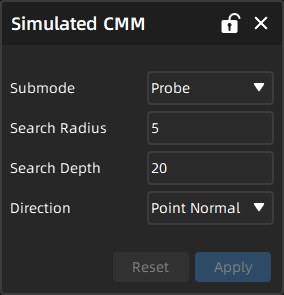
- Select a submode (probe / disk) and direction (point normal / customize), and customize the search radius (mm) and search depth (mm).
- After completing relevant settings, you can click on the model in the 3D scene to create points; Then click Apply to save the reference point feature, and the
 reference point object will be displayed in the
  feature module in the left-side tree view.
 - Right-click on that point feature group in the left-side tree view, select Extract Measured Features and determine the measured model on which the feature will be extracted.
- In the Point window, select an align mode and click Apply to create the corresponding measured point feature.
- The
 measured point object will be displayed in the corresponding point feature group in the left-side tree view.
Col
Anchor
Directly anchor points on the model to create point features.
Note
- Before creating point features using the anchor method, please import a reference model or a measured model.
- This method can only create reference features.
- If you need to extract features to generate feature pairs, please import at least one measured model.
The steps for creating point features through anchor as well as extracting measured features are as follows:
- Select Anchor in the drop-down list of Point to enable the anchor tool.
- Click on the model in the 3D scene to create, and click Apply in the Anchor window to save the reference point feature, and the reference point object will be displayed in the feature module in the left-side tree view.
- Right-click on that point feature group in the left-side tree view, select Extract Measured Features and determine the measured model on which the feature will be extracted.
- >In the Point window, select an align mode and edit parameters including max distance, and click Apply to create the corresponding measured point feature.
- The measured point object will be displayed in the corresponding point feature group in the left-side tree view.
Extreme Position
Usually, when inspecting irregular workpieces, it is necessary to measure distances between two extreme positions. In such cases, you can use this feature to create point features at the extreme positions.
Note
- Before creating point features using the extreme position method, please import a reference model.
- This method can only create reference features.
- If you need to extract features to generate feature pairs, please import at least one measured model.
The steps for creating point features through extreme position as well as extracting measured features are as follows:
Col
- Select Extreme Position in the drop-down list of Point to enable the extreme position tool.
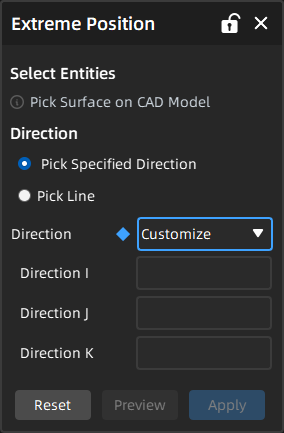
- Click on the CAD model in the 3D scene to pick a surface where the extreme position points need to be created, and this surface wil be determined as the calculation region.
- Select direction in the window of Extreme Position:
- Pick specified direction: support customizing direction or selecting X / Y / Z axis.
- Pick line: select a created line feature.
- After completing relevant settings, click Preview to preview the extreme position point to be created; Then click Apply to save the reference point feature, and the reference point object will be displayed in the feature module in the left-side tree view.
- Right-click on that point feature group in the left-side tree view, select Extract Measured Features and determine the measured model on which the feature will be extracted.
- In the Point window, select an align mode and edit parameters including max distance, and click Apply to create the corresponding measured point feature.
- The measured point object will be displayed in the corresponding point feature group in the left-side tree view.
Col
Line
In the Create Features toolbar, clickLine to expand the drop-down list, where you can select Numerically creation method.
Note
- Before creating line features, please import a reference model.
- This method can only create reference features.
- If you need to extract features to generate feature pairs, please import at least one measured model.
The steps for creating line features as well as extracting measured features are as follows:
Col
- Select Numerically in the drop-down list of Line to open the corresponding window.
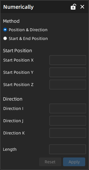
- Select a method:
- Position & Direction: Customizing the start position X / Y / Z, direction and length.
- Start & End position: Customizing the X / Y / Z of start & end position.
- Click Apply to save the reference line feature, and the
 reference line object will be displayed in the feature module in the left-side tree view.
 - Right-click on that line feature group in the left-side tree view, select Extract Measured Features and determine the measured model on which the feature will be extracted.
- >In the Line window, select an align mode, edit parameters including max distance and boundary exclusion distance, as well as set eliminate noise, and click Apply to create the corresponding measured line feature.
- The
 measured line object will be displayed in the corresponding line feature group in the left-side tree view.
Col
Plane
In the Create Features toolbar, clickPlane to expand the drop-down list, where you can pick Single / Multiple plane on CAD model.
Note
- Before creating plane features, please import a reference model.
- This method can only create reference features.
- If you need to extract features to generate feature pairs, please import at least one measured model.
The steps for creating plane features as well as extracting measured features are as follows:
- In the drop-down list of Plane, select Pick on CAD Model > Single Plane / Multiple Planeto enable the plane feature creation tool.
- Click on the highlighted plane of the model in the 3D scene to create, and click Apply in the window of Single Plane / Multiple Plane to save the reference plane feature, and the
 reference plane object will be displayed in the feature module in the left-side tree view.
 Note
Note
If you select multiple plane, only multiple planes in one plane can be selected. - Right-click on that plane feature group in the left-side tree view, select Extract Measured Features and determine the measured model on which the feature will be extracted.
- In the Plane window, select an align mode, edit parameters including max distance and boundary exclusion distance, as well as set eliminate noise, and click Apply to create the corresponding measured plane feature.
- The
 measured plane object will be displayed in the corresponding line feature group in the left-side tree view.
-
A CMM probing system generally consists of a probe head and a touch-trigger probe. The probe makes slight contact with the surface of the measured workpiece, and by measuring the position of the probe in a three-dimensional coordinate system, the coordinates of the measurement points on the workpiece are obtained. ↩