Linear and Angular Dimension
Click Dimension in the top navigation bar to enter the dimension module, where you can perform  linear dimension and
  angular dimension.
Linear Dimension
Support measuring the straight-line distance from point to point, point to plane, point to line, and line to line, and automatically generating labels to display the measured value, deviation, and tolerance.
Note
Please ensure that you have pairs of corresponding features, meaning they should include at least the reference feature or the measured feature simultaneously.
The steps to perform linear dimension are as follows:
Col
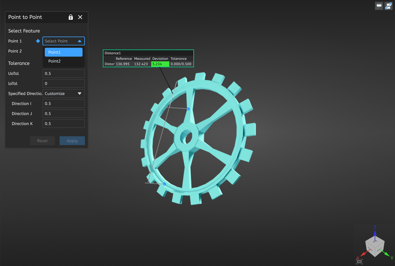
- In the Dimension Tools bar, clickLinear Dimension to expand the drop-down list, where you can select Point to Point / Point to Plane / Point to Line / Line to Line to open the corresponding window.
- Select the feature to be used for performing measuring, and select the upper and lower tolerance as well as the specified direction (3D distance, X / Y / Z axis or customize).
 Note
Note- Point features can also be selected as existing circles or spheres, in which case the center of the circle or sphere is taken.
- Line features can also be selected as existing cylinders or cones, in which case the axis line is taken.
- The upper tolerance must be greater than the lower tolerance, and the value range is -100 to 100.
- Click Apply, the software will automatically calculate the distance and deviation between the two features and display labels in the 3D scene based on the tolerance: Green indicates that the deviation is within the tolerance range, while red indicates that the deviation is outside the tolerance range.
- The linear dimension object will be displayed in the
 dimension module in the left-side tree view.
Col
Angular Dimension
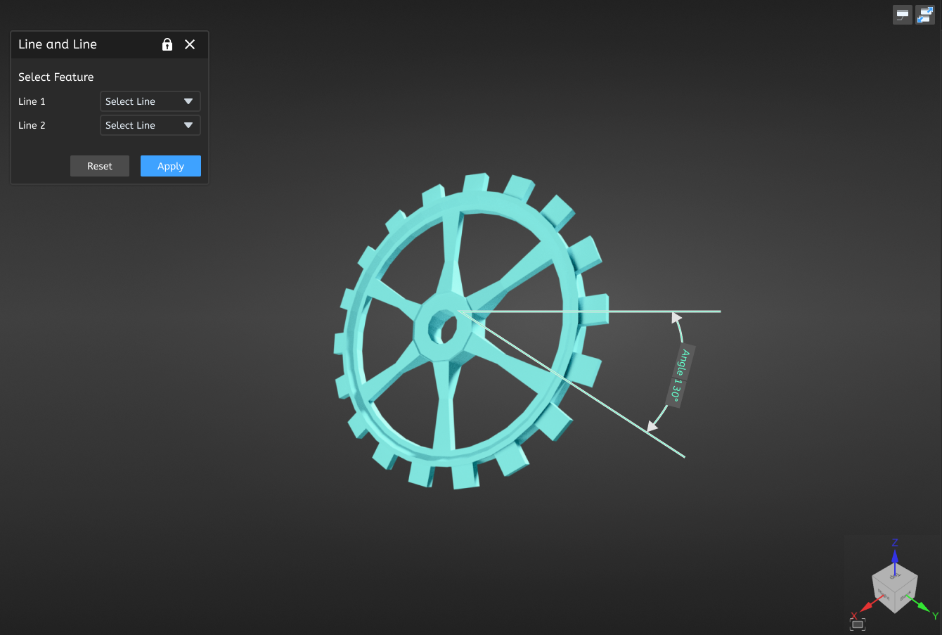
Support measuring the angle from line to line, line to plane, and plane to plane, and automatically generating labels to display the measured value, deviation, and tolerance.
Note
Please ensure that you have pairs of corresponding features, meaning they should include at least the reference feature or the measured feature simultaneously.
The steps to perform angular dimension are as follows:
Col
- In the Dimension Tools bar, clickAngular Dimension to expand the drop-down list, where you can select Line to Line / Line to Plane / Plane to Plane to open the corresponding window.
- Select the feature to be used for performing measuring, and select the upper and lower tolerance.Note
The upper tolerance must be greater than the lower tolerance, and the value range is -100 to 100. - Click Apply, the software will automatically calculate the angle and deviation between the two features and display labels in the 3D scene based on the tolerance: Green indicates that the deviation is within the tolerance range, while red indicates that the deviation is outside the tolerance range.
- The angle dimension object will be displayed in the dimension module in the left-side tree view.
Col