Settings
You can adjust scan settings during pre-scanning or scanning, including the mode, light source, object, brightness and so on, to achieve an ideal result.
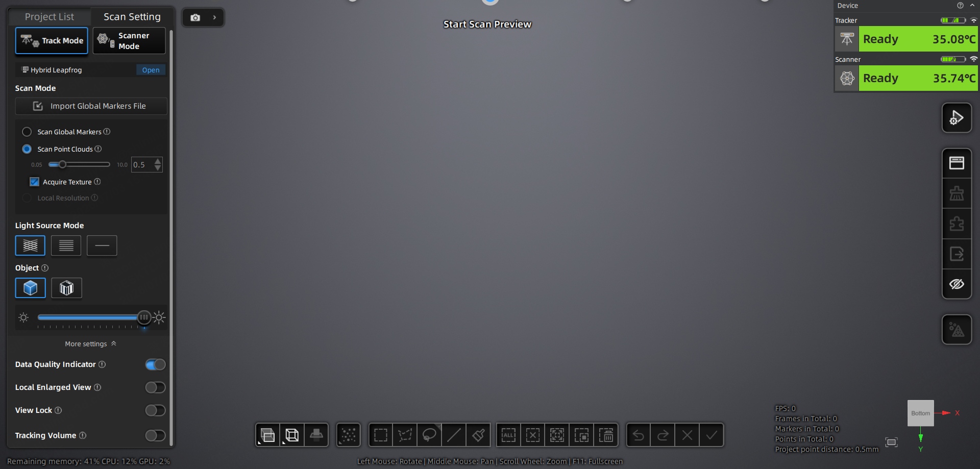
Scan Mode
Trak Mode
This mode requires the tracker to be used together with the scanner for scanning. Once you select Trak Mode, you can select Scan Point Cloud, Local Resolution and Scan Global Markers/Photogrammetry to scan.
Note
- Photogrammetry mode is only supported by EinScan Trak Pro.
- In Trak Mode, scanning point cloud does not require pasting markers; this mode is suitable for medium to large scene scanning.
Scanner Mode
After selecting Scanner Mode, you can use the scanner alone to perform Scan Point Cloud, Local Resolution and Scan Global Markers.
Note
- Scanner mode is suitable for small to medium-sized object scanning scenarios.
- Please remove the ball frame before using Scanner Mode for scanning.
- In Scanner Mode, scanning using marker alignment requires pasting markers on the object before scanning. For marker placement precautions, please refer to the Scan Preparation section.
Acquire Texture
When enabled, texture data will be acquired during scanning.
Note
This option appears after selecting Scan Point Cloud mode.
Texture Camera Window
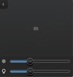
Click  > to expand the texture camera window and adjust the camera brightness.
Col
Note
- The texture camera window appears after enabling Acquire Texture.
- It is recommended to perform white balance calibration before texture scanning.
- When scanning textures, you can adjust the
 brightness by dragging the
  slider or clicking different positions on the brightness bar in the texture window.
 - When scanning textures in low-light conditions, you can adjust the
 texture fill light intensity by dragging the slider or clicking different positions on the brightness bar in the texture camera window.
Col
Align Mode
| Align Mode | |
|---|---|
| Feature Alignment | Aligns the scanned object's surface features automatically. This function is suitable for objects with detailed surface features or for those that cannot have markers placed. |
| Marker Alignment | Completes alignment using markers, suitable for objects with distinct geometric features, flat areas with minimal geometric features, and scenes requiring accuracy. |
Note
- This option appears after selecting Scanner Mode > Scan Point Cloud.
- Within a project group, each project only supports using one alignment mode.
Working Distance
Drag the slider to adjust the working distance. This function sets the farthest and nearest scanning distances of the device. During scanning, only data within the working distance will be scanned and generated, effectively filtering out unwanted distant or close noise data and improving data processing efficiency.
Note
This option appears after selecting Feature Alignment mode.
Plane Detection
When scanning detects planar or near-planar areas, it will not scan those data, reducing the probability of misalignment of planes or features.
Note
This function can only be enabled when Feature Alignment mode is selected.
Resolution
In Scan Point Cloud mode, you can adjust the point distance of the current project by the slider. A smaller point distance means higher point cloud resolution, but also requires higher computer hardware specifications. For objects with rich surface features, set a smaller point distance; for smoother surfaces, a larger point distance is recommended.
Note
- Multiple projects with different point distances can be created within the same project group.
- When the point distance ≤ 0.2 mm, the device's light source mode will automatically switch to
 parallel line mode.
 - After adjusting the point distance of the current project, the Data Quality Indicator will be automatically enabled. You can perform additional scanning on insufficiently scanned areas (yellow areas) based on the indicator.
Marker Size
Supports 6 mm and 12 mm diameter markers (all selected by default). You can check the corresponding marker size based on your scanning needs. Once checked, only markers matching the selected size will be captured during scanning.
Note
- Please select at least one marker size.
- This option appears after selecting Scan Global Markers or Photogrammetry mode.
- The marker size cannot be changed during preview, scanning, pause, and editing states.
- In Trak mode, if you only checked 6 mm, scanned 6 mm markers will not be used for alignment in Scan Markers or Photogrammetry mode. Switching to Scan Point Cloud mode will prompt you to clear the data.
Light Source Mode
| Mode | Description |
|---|---|
 |
This mode is mainly used for fast scanning of large objects. |
|
This mode is mainly used for fine detail scanning. |
 |
This mode is mainly used for scanning deep holes and gaps. |
Note
This option appears after selecting Scan Point Cloud mode.
Object
Select the material that matches the object to be scanned. It is recommended to adjust the brightness after setting the scanning object.
Note
- This option appears after selecting Scan Point Cloud mode.
- For transparent or light-absorbing objects, it is recommended to apply powder spray in advance and use
 Normal Mode for scanning.
 - For highly reflective objects, select
 Reflect Mode for scanning.
Brightness
Scanning brightness refers to the intensity of light that is projected onto the object being scanned when using the device. If the brightness is too high or too low, it can affect the quality and integrity of the scanning data. Therefore, it is recommended that you adjust the brightness before or during scanning until a relatively complete laser line (in Scan Point Cloud or Local Resolution mode) or a large number of non-flickering markers (in Scan Global Markers or Photogrammetry mode) are reconstructed to ensure optimal scanning results.
- In Scan Global Markers or Photogrammetry mode, you can select Low, Medium, or High brightness levels.
- In Scan Point Cloud or Local Resolution mode, you can drag the slider to adjust the scanning brightness.
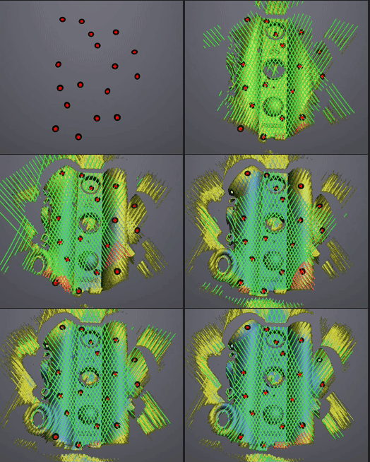
Data Quality Indicator
The quality of the scanned data is shown by a color indicator. Blue represents high-quality scanned data, and yellow indicates insufficient data where further scanning is required. If these areas are not scanned adequately, the insufficient data may disappear or be abnormal after post-processing.
Note
- This option appears after selecting Scan Point Cloud mode.
- The model only displays the quality color map in the scanning interface; it will no longer display the quality color map after entering the wrap or post-processing interface.
- Changing the point distance will affect the existing color display. Please rescan the insufficiently scanned areas after changing the point distance.
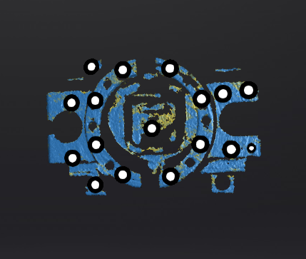
Local Enlarged View
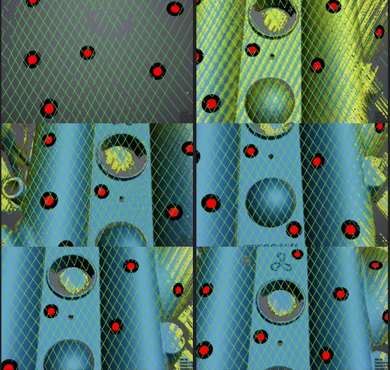
When enabled, the scanning interface only displays the local perspective of the scanned object, which can be used for supplementary scanning of small holes.
Note
- This option appears after selecting Scan Point Cloud or Local Resolution mode.
- Long press the
 button on the device to quickly enable or disable the Local Enlarged View function.
View Lock
When enabled, the 3D scene on the scanning interface will no longer follow the movement of the scanner, which can be used for scanning the current surface of the object.
Note
- This option appears after selecting Scan Point Cloud or Local Resolution mode.
- Long press the
 button on the device to quickly enable or disable the View Lock function.
Tracking Volume
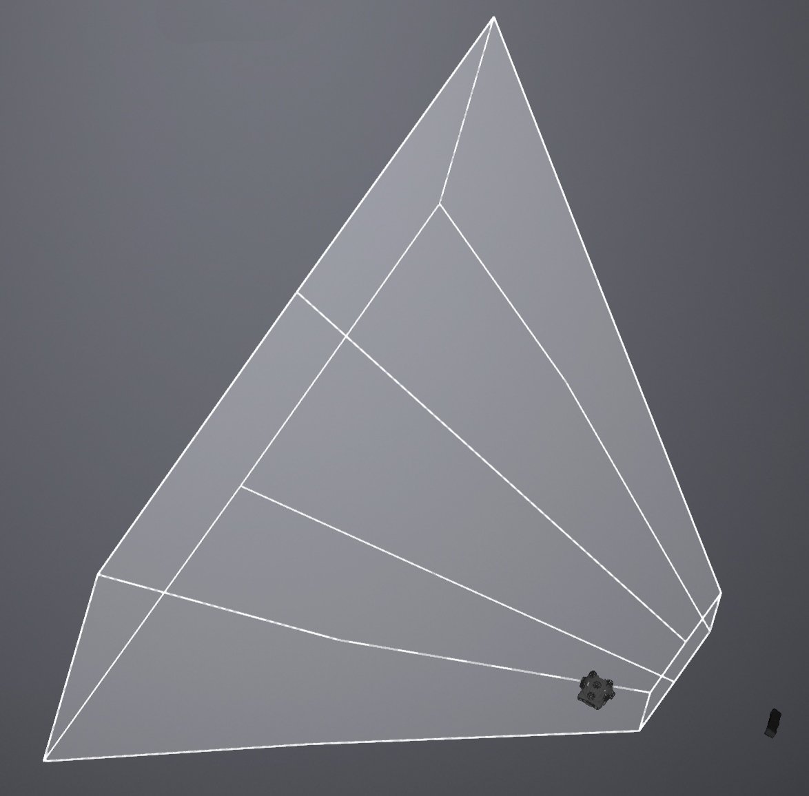
When the scanner is outside the tracker's field of view, the scanner may not be able to scan data or the quality of the scanned data may be poor. In such a situation, you can enable this function. Once enabled, the tracker's field of view will be visualized in the 3D scene, allowing you to see the relative positions of the tracker, scanner, and the object being scanned, ensuring that the object and the scanner are within the tracker's field of view.
Note
This function can only be enabled in Trak Mode.