Data Editing
After pausing scanning, you can use the editing tools and right sidebar functions in the scanning interface to edit the data and generate accurate 3D point cloud data.
Editing Toolbar
After pausing scanning or completing scanning, you can use the following tools to edit the data.

| Function | |
|---|---|
 Perspective View |
View the model in Perspective mode. In this mode, objects appear larger when closer and smaller when farther away, consistent with normal human observation of the 3D world. Click again to switch to Orthogonal View. |
 Orthogonal View |
View the model in Orthogonal mode. In this mode, there is no perspective effect, and the object size is independent of the viewpoint distance. Click again to switch to Perspective View. |
 Multi View |
Switch among six different view angles to view the scanned data. |
 Cutting Plane |
Create a cutting plane to quickly segment data and filter redundant data. |
| Function | |
|---|---|
 Point Cloud Edit |
In this mode, use the selection tool to select point cloud data. Click again to switch to Edit Markers mode. Note NoteMultiple undo or redo operations are supported. |
 Edit Markers |
In this mode, use the selection tool to only select markers data. Click again to switch to Point Cloud Edit mode.Note |
| Function | |
|---|---|
 Rectangular |
Select or deselect data in a rectangular area. |
 Polygon |
Select or deselect data in a polygon area. |
 Lasso |
Select or deselect data using a lasso. |
 Line |
Select or deselect data using a straight line. |
 Brush |
Select or deselect data using a brush. |
| Function | Function | ||
|---|---|---|---|
 Select All |
Select all data on the current interface. |  Unselect |
Deselect all. |
 Connected Domain |
After selecting any piece of data, click this button to select all data connected to that area. |  Invert |
Select all currently unselected data. |
 Delete Selected |
Click to delete the currently selected data. |
| Function | Function | ||
|---|---|---|---|
 Undo Delete |
Undo the most recent deletion and restore the most recently deleted data. Click multiple times to undo multiple deletions. |
 Redo |
Restore the last operation. Click multiple times to restore multiple operations. |
 Cancel Edit |
Undo all editing operations. |  Apply Edit |
Apply all editing operations. |
Caution
After applying edit operations, it will be impossible to restore the initial state. It can only be restored by reloading the file.
Cutting Plane
You can create a cutting plane to remove the base data of the object during scanning.
Create Cutting Plane
-
On the editing toolbar at the bottom of the interface, click
to enter the cutting plane tool interface. -
Select the creation method and follow the interface prompts to create the cutting plane.
Method Description Fitting Point Cloud Uses the plane formed by the selected data as the cutting plane. Creating Straight Line Uses the plane where the created line lies as the cutting plane. By Markers Uses the plane formed by the selected markers (at least 3) as the cutting plane. -
Click Create to create the cutting plane; click Cancel to cancel all operations and exit the cutting plane tool interface.
Note
- When saving a markers file, the cutting plane will be saved together.
- The cutting plane created in the current project is only effective for that project.
- After creating a cutting plane, data below the cutting plane will no longer be collected.
- Cutting planes can be created after opening a markers file or scanning markers (before and after optimization).
Edit Cutting Plane
Col
-
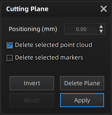
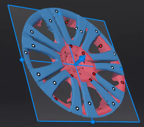
Delete the selected point cloud / markers: When checked, the point cloud data / markers to be deleted will appear in red. After applying the edit, the red point cloud data / markers will be deleted.
Caution
- It is not supported to delete all point cloud data.
- At least 4 markers should be retained on the front side of the cutting plane.
- Unable to uncheck Delete the selected point cloud in the current version.
-
Invert Selection: Flip the cutting plane to reverse the selection of data to be retained.
- Delete Plane: Delete the current cutting plane and return to the create cutting plane interface.
- Reset: Reset all operations performed after creating the cutting plane.
- Apply: Apply all editing operations.
Col
Col
Col
- Translate Cutting Plane: Drag the normal arrow on the cutting plane
 or enter the translation distance (unit: mm) in the value box to translate the cutting plane.
 - Rotate Cutting Plane: Drag the sphere on the cutting plane
 , using the opposite axis of the currently selected sphere as the center axis for rotation.
Right Sidebar
| Function | |
|---|---|
 Preview |
Only preview, the scanned data is not saved. In preview mode, you can set scan parameters based on the scanning effect. You can enable or disable Preview by clicking  in the upper right corner to open the settings interface. When disabled, this button will not appear on the scanning interface. in the upper right corner to open the settings interface. When disabled, this button will not appear on the scanning interface. |
 Scan |
Start scanning, the scanned data will be saved to the specified path. Caution Caution |
 Pause |
Pause scanning. You can edit the scanned data. |
| Function | Function | ||
|---|---|---|---|
 Project Group |
Create or open a project group. |  Delete Data |
Delete the data on the current interface. |
 Align |
Align the project data as needed. |  Export Data |
 : Save the scanned data locally in the specified format. : Save the scanned data locally in the specified format. : If you have installed EXModel, click this button to switch to EXModel, and the model data will be automatically imported. : If you have installed EXModel, click this button to switch to EXModel, and the model data will be automatically imported. |
 Texture |
Show or hide the model texture. |  Mesh |
|
| Click to enter the mesh process. |
Shortcut
| Shortcut | |
|---|---|
| Hold Left Button and move cursor | Rotate the model |
| Hold Middle Button and move cursor | Pan the model |
| Shift+left mouse button | Select data |
| Ctrl+left mouse button | Deselect data |
| Scroll wheel | Zoom in/out the model |
| Spacebar | Confirm editing when editing data |
| Del | Delete selected data |
Context Menu
| Function | |
|---|---|
| Select All / Unselect / Invert Selection / Delete Selected Data | Same as the Editing Toolbar functions, can be operated via shortcuts. |
| Zoom to Fit | Display the data centered with an appropriate size on the interface. |
| Connected Domain | Same as the Editing Toolbar function. |
| Set Rotate Center | Set the rotation center on the data by clicking with the left mouse button. Press Esc to exit. |
| Reset Rotate Center | Reset the rotation center back to the data center. |