Dent Inspect
Dent Inspect is a surface defect detection technology based on 3D scanning data, capable of accurately identifying and quantifying irregular defects such as protrusions and dents on the surface of workpieces. By utilizing the dent inspect function, it effectively enhances product quality control levels, promptly identifies potential defects, and provides data support for quality decision-making.
Function Description
You can import data, adjust effects, and complete detection through the following functions.
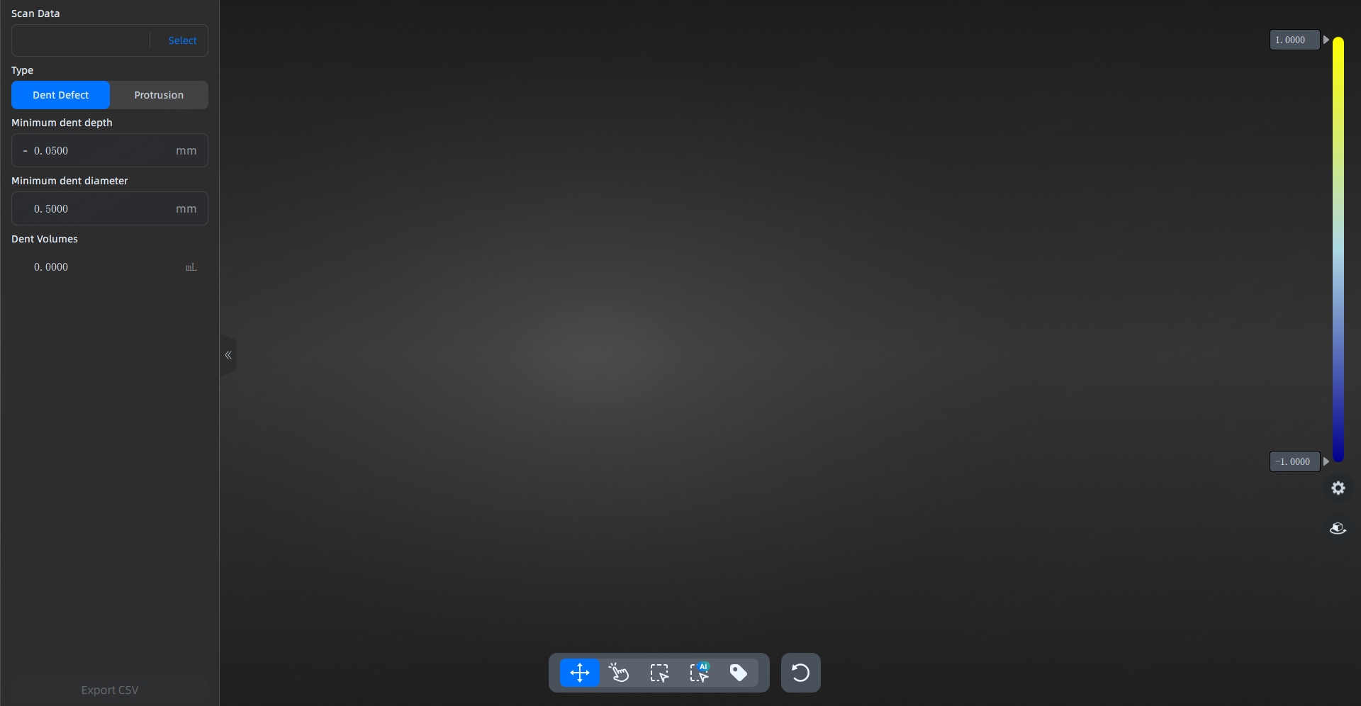
Scan Data
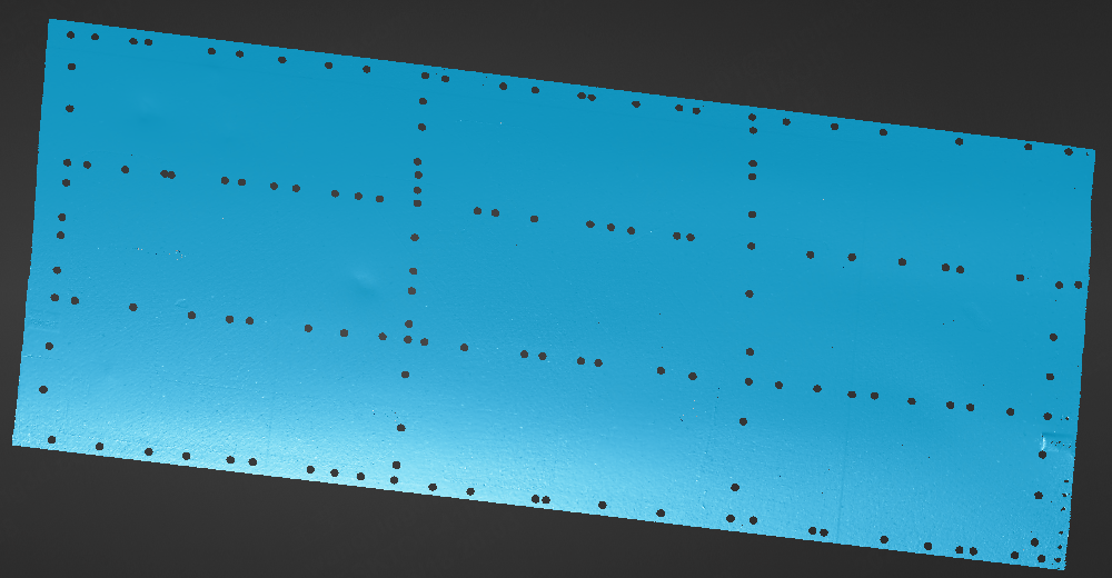
You can select the files to import (STL, PLY, OBJ).
Types
Supports two types of detection: dent defect and protrusions; after selecting the detection type, you can set the minimum detection value.
Toolbar
| Function | |
|---|---|
| You can rotate the model by pressing and holding the left mouse button and moving it. | |
| Click on the dents or protrusions on the model to inspect them. | |
| Press and hold the left mouse button and move to select a region, automatically inspecting the dents or protrusions within the selected area. | |
| Press and hold the left mouse button and move to select a region, using AI to automatically inspect the dents or protrusions within the selected area. | |
| Click the left mouse button in the detected dent or protrusion area to add a value label (unit: millimeters). | |
| One-click to clear all detection results on the current interface. | |
| After selecting a dent or protrusion detection item, click this button to clear this measurement item. |
Color Bar
On the right color bar, you can click the input box with the left mouse button to enter values and adjust the value range. After adjusting the values, the color map in the 3D scene will update in real-time.
 Settings
Dent
You can show or hide the dent inspection items.
Labels
You can hide or select the label display type in the 3D scene.
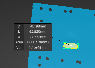
- Minimal labels: Only show the minimum dent depth or minimum protrusion height (D).
- Full labels: Show the minimum dent depth or minimum protrusion height (D), dent or protrusion length (L), dent or protrusion width (W), area (Area), and volume (Vol).
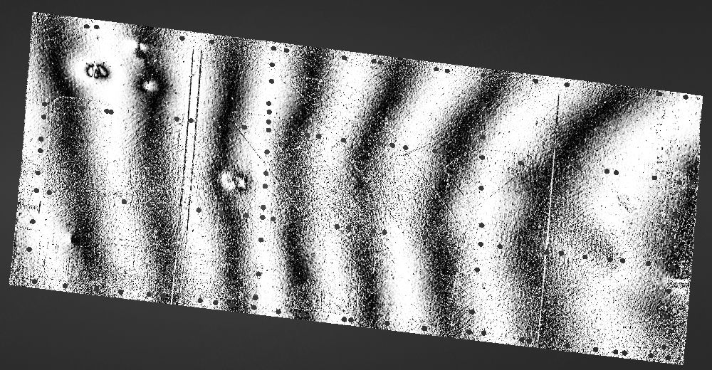
Zebra Line
Simulate the light reflection stripes on the model to allow for a quick and intuitive view of various defects.
Note
You can adjust the clarity and width of the reflection lines through the smooth and width parameters under this function, making the dents or protrusions more noticeable.
Col
Off
Col
On
Fit View
Click ![]() to automatically center the model and adjust the model view size to fit the screen size.
to automatically center the model and adjust the model view size to fit the screen size.
Operation Instructions
- In the upper left corner of the interface, select the file to be detected for import.
- On the left side of the interface, select the detection type as dent defect or protrusion and set the minimum detection value.
-
Move and rotate the model to view the defect from multiple angles.
Operation Description Press and hold the left mouse button In non-selection mode, press and hold the left mouse button and move to rotate the model for viewing. Press and hold the mouse wheel Press and hold the mouse wheel and move to pan the model for viewing. Press and hold the right mouse button Press and hold the right mouse button to rotate the model for viewing. Note
If the model's dents or protrusions are difficult to detect directly, you can enable the
> Zebra Line function. This function will clarify the model's dents or protrusions for easier viewing. -
Use the toolbar's
 tool or
  /
/  tool to select the dent or protrusion; the software will automatically measure and display the dent or protrusion data at that location.
Note
If you need to re-inspect a certain dent or protrusion, you can select that area and click
 to clear that detection item.
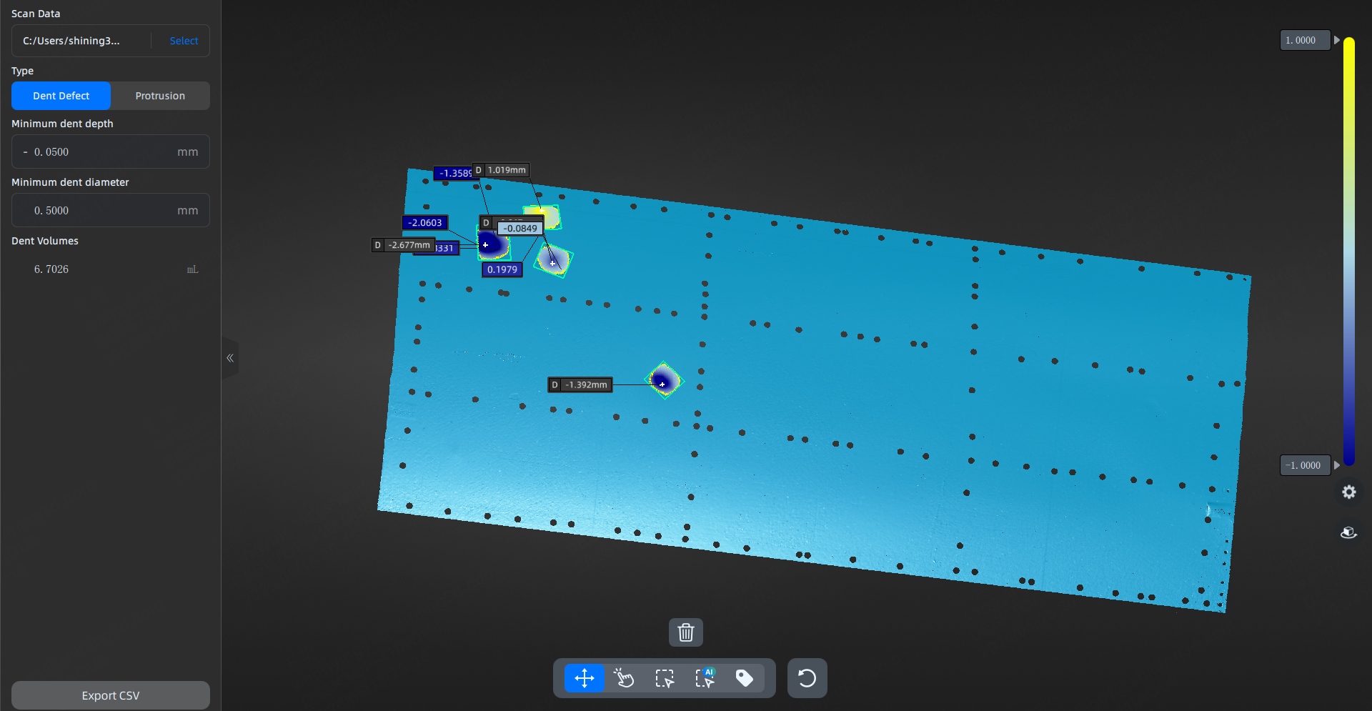
-
After the detection is complete, click the Export CSV button at the bottom left of the interface to export the detection data.