CMM Creation
A CMM probing system generally consists of a probe head and a touch-trigger probe. The probe makes slight contact with the surface of the measured workpiece, and by measuring the position of the probe in a three-dimensional coordinate system, the coordinates of the measurement points on the workpiece are obtained.
This method creates features by simulating actual CMM (Coordinate Measuring Machine) probing methods such as rectangular probing, probe contact, or disk contact.
Note
- The CMM creation method is applicable to creating point features.
- Before creating features, please import a reference model or measured model.
- If the imported data is point cloud data (ACS, TXT, XYZ, and P3), the CMM method cannot be used to create features.
Creation Steps
- Select
 CMM in the drop-down menu of
  Point to open the corresponding window.
 -
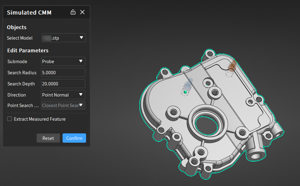
Select one of the following sub-modes:
- Rectangle: Select a constraint plane (XY plane / XZ plane / YZ plane / a created plane feature), customize the search depth (mm), length (mm) and width (mm), select a direction (point normal / X axis / Y axis / customize), and define the feature as Reference Feature or Measured Feature.
- Probe or Disk: Select a direction (point normal / customize), customize the search radius (mm) and search depth (mm), and define the feature as Reference Feature or Measured Feature.
Note
If the sub-mode is Rectangle, the selected constraint plane cannot be perpendicular to the search direction.
-
After completing the relevant settings, click on the model in the 3D scene to create points; then click Confirm to create the new feature; the object will be displayed in the left tree view.
Note
When the alignment used is consistent with the current active alignment, the label displays directional deviation; values within the deviation range are displayed in green, and values outside the deviation range are displayed in red.
Extract Measured Values
After creating reference features, the corresponding measured features can be extracted automatically or manually.
Note
Import at least one measured model before extracting measured features to generate feature pairs.
-
Automatic Extraction: Enable Auto Extraction of Measured Values via
 Settings in the upper right corner of the software interface or check
  Extract Measured Feature in the creation window. The software will automatically extract the corresponding measured feature with default parameters after creating any reference feature.
Note
If there are multiple measurement objects, please select the corresponding extraction object in the creation window; the default selection is the first measured model or the first measured model within the first measurement group.
-
Manual Extraction: After creating a reference feature, right-click the feature group in the tree view on the left, select Extract Measured Feature and specify the measurement model to be extracted; you can specify Align Object in the extraction pop-up window.
Note
When selecting sub-features, 2D features, or when there are only sub-features or 2D features in multiple selections or groups, right-click the feature group in the left tree view and select Extract Measured Feature to directly extract the measured feature without selecting a measured model.