Scan
Use the scan function for data scanning or feature probing.
Note
It is recommended to complete calibration in the scanning software before using the device for scanning or probing.
Device Connection
Auto Connection
If SHINING3D Inspect is started from scanning software, it will automatically connect to the scanning device. After successful connection, the device's online status will be displayed in real-time in the upper right corner ( /
/
); if the device goes offline (
/
/
), it will automatically reconnect. If it fails to connect for a long time, please restart the software or contact technical support.
Manual Connection
If SHINING3D Inspect is started independently, you need to click
, select the device to be connected from the drop-down list; after successful connection, the device's online status will be displayed in real-time in the upper right corner ( /
/
); if the device goes offline (
/
/
), it will automatically reconnect. If it fails to connect for a long time, please restart the software or contact technical support.
Disconnect
If you need to disconnect the device, click Disconnect in the upper right corner of the interface.
Scan Global Markers
You can choose Trak Nova device for markers scanning.
Scan Mesh
You can choose Trak Nova device for data scanning.
Scan Preset
After selecting the scanning device, you need to select the scanning software path and project file storage path in the preset pop-up window.
Scan Settings
After completing the preset, before scanning, you can set scan parameters to obtain better scanning results.

Point distance Setting
Before scanning and after pausing scanning, you can drag the slider or enter values to adjust the point distance in real-time.
Light Source Mode
| Light Source Mode | |
|---|---|
| Cross Line | This mode is mainly used for fast scanning of large objects. |
| Parallel Line | This mode is mainly used for fine scanning. |
| Single Line | This mode is mainly used for deep hole and gap scanning. |
Scan Object
You can choose different scan object modes according to different object materials.
Brightness
Scanning brightness refers to the intensity of light that is projected onto the object being scanned when using the device. If the brightness is too high or too low, it can affect the quality and integrity of the scanning data. Therefore, it is recommended that you adjust the brightness by dragging the slider before or during the scanning process until relatively complete laser data is reconstructed, ensuring optimal scanning results.
Quality Chromatogram
The quality of the scanned data is shown by a color indicator. Blue represents high-quality scanned data, and yellow indicates insufficient data where further scanning is required. If these areas are not scanned adequately, the insufficient data may disappear or be abnormal after post-processing.
Note
Changing the point distance will affect the existing color display. Please rescan the insufficiently scanned areas after changing the point distance.
Reference Data Crop
After checking, the scanned data will be automatically cropped using the selected reference model after scanning is completed.
Scan Steps
-
Click Scan > Scan Mesh in the navigation bar or select Go to Scan from the tree view right-click menu.
Note
- If the current measurement object was obtained by scanning with this software, you can use this function to perform supplementary scanning on the current measurement object or directly add a new measurement object; the newly added measurement object will be grouped with the current measurement object and apply the same alignment status.
- If the current measurement object was not obtained by scanning with this software, you can use this function to scan and then replace the current measurement object or add a new measurement object; after scanning is completed, the newly added measurement object will be grouped with the current measurement object and apply the same alignment status.
- If the current measurement object was obtained by scanning with this software, you can also select Go to Scan from the tree view right-click menu.
-
In the pop-up window, select the scanning software path and project file storage path.
- Perform scan settings, specific setting descriptions please refer to the above Scan Settings.
-
Click Scan or press the scan button on the device to start scanning.

-
After starting scanning, click Pause or press the scan button on the device to pause scanning; click Scan again or press the scan button on the device again to continue scanning.
- After scanning is completed, click Confirm to add this scan data to the tree view. If you are not satisfied with the current scanning effect, you can click Rescan to scan again.
Probe Features
Use the probe to create new features by point probing.
Note
- Before creating features using the probe method, please import a reference model or measured model.
- Probe features apply to creating point, line, plane, circle, sphere, cone, and cylinder features.
Creation Steps
- Click Scan > Probe Features in the navigation bar or select Probe Features from the tree view right-click menu.
- Select the feature to be created and edit parameters.
-
According to the interface prompts, use the probe to probe points.

-
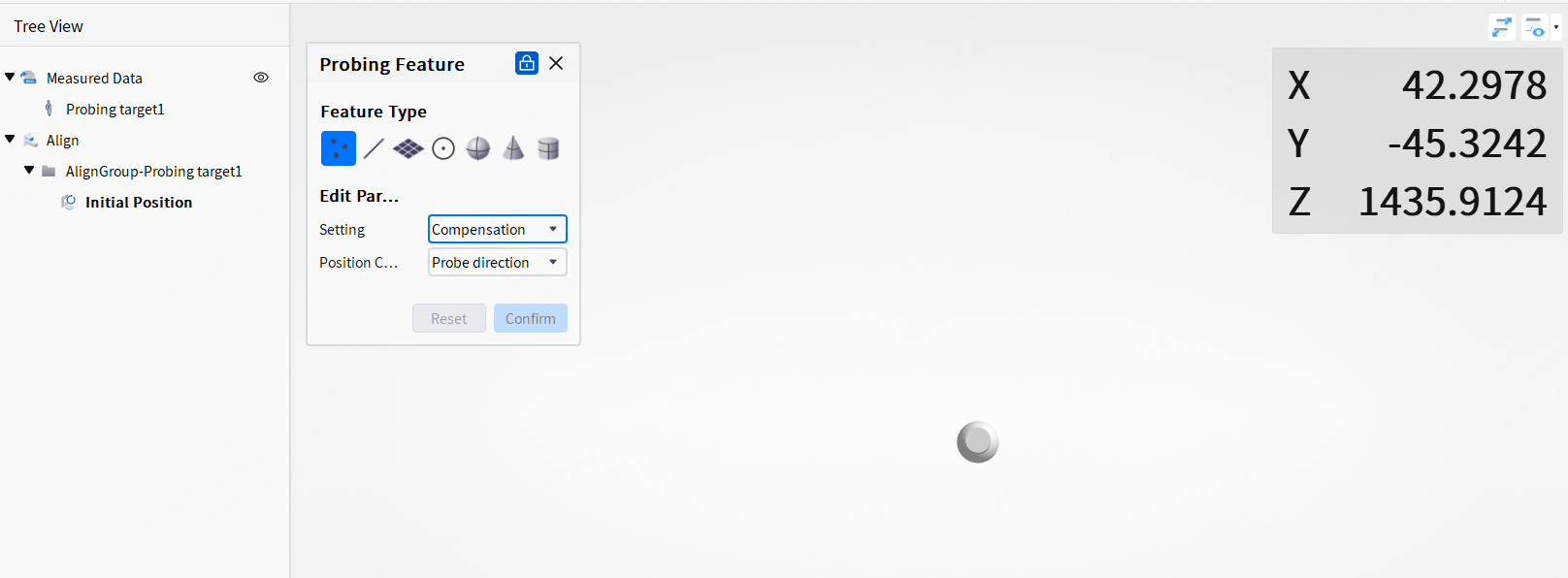
After using the probe to probe points, relevant features will be automatically fitted. Click Confirm to create a new feature.
Note
- Support multiple point probing to create multiple features.
- Before pressing the Confirm button, you can undo the points that have been probed. If you have Confirmed creation, you can delete the corresponding point features in the left tree view.
Track Tracking
When the probe is successfully connected, you can use the track tracking function. By setting the tracking time interval, the software will automatically record the point coordinates during the tracking process. After tracking is completed, the point coordinates can be exported as TXT files.