Measurement
Click Measurement in the top navigation bar to enter the measurement module, where you can perform ![]() Caliper Measurement,
Caliper Measurement, ![]() Area Measurement,
Area Measurement, ![]() Volume Measurement,
Volume Measurement, ![]() Thickness Measurement and
Thickness Measurement and ![]() Trim/Hemming Edge Measurement.
Trim/Hemming Edge Measurement.
Note
Only supports measuring mesh models.
Caliper Measurement
Col
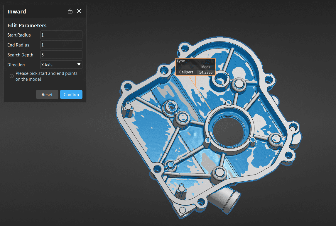
- In the measurement toolbar, click
 Caliper Measurement to expand the drop-down list, and select Caliper Measurement - Inside / Caliper Measurement - Outside to open the corresponding window.
 - Edit the start radius (0 < x ≤ 50) and direction.
- After completing the relevant settings, click on the model in the 3D scene to select the start and end points.
- Click Apply to save the caliper, and the caliper object will be displayed in the
 measurement module in the left-side tree view.
Col
Note
- When creating a caliper, both the start and end points must be selected, otherwise it will prompt "
 Caliper measurement cannot be performed at the current position".
 - To delete the currently created caliper measurement, select the caliper measurement and press Del.
- Multiple caliper measurement items can be created at once. After clicking Confirm, the created multiple caliper measurement items will be displayed as a measurement group in the tree view.
Area Measurement
Col
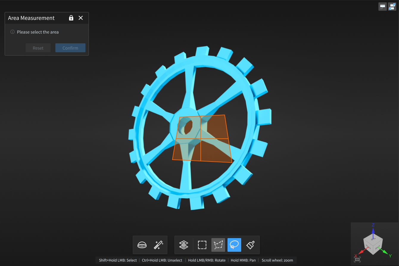
- In the measurement toolbar, click
 Area Measurement to open the corresponding window.
 - Select tools in the toolbar under the 3D scene, then select the area to be measured on the model.
- Click Confirm, and the label will be displayed in the 3D scene, and the area object will be displayed in the measurement module in the left-side tree view.
Col
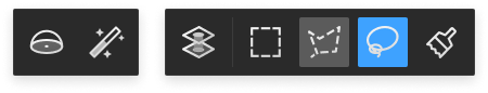
Introduction to toolbar and shortcuts is as follows:
| Icon | Name | Description |
|---|---|---|
| Sphere Selection | Select mesh vertices on the surface of the mesh model to choose the fitting area. Note NoteAfter enabling this function, other selection tools and the select through function cannot be used. |
|
| Magic Wand | Automatically select adjacent areas on the mesh model according to curvature.Note |
|
| Select Through | Disabled by default, when enabled, it selects both the front and back areas of the model; otherwise, only the visible surface is selected. | |
| Rectangle Selection | Select or deselect data areas in the form of |
|
| Polygon Selection | Select or deselect data areas in the form of |
|
| Lasso | Select or deselect data areas in the form of |
|
| Brush | Use brush (supports size adjustment) to select or deselect data areas. |
| Function | Shortcut |
|---|---|
| Select | Shift+left mouse button |
| Deselect | Ctrl+left mouse button |
| Adjust brush size | Shift+middle mouse button |
Note
For other shortcut operations on the model, please click ![]() > Shortcut Instructions in the top right corner of the interface.
> Shortcut Instructions in the top right corner of the interface.
Volume Measurement
Col
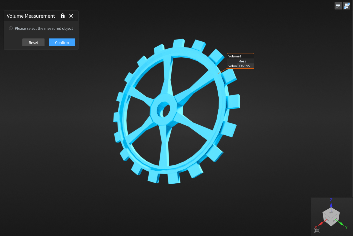
- In the measurement toolbar, click
 Volume Measurement to open the corresponding window.
 - Click to select the model in the 3D scene, then click Confirm, and the label will be displayed in the 3D scene, and the volume object will be displayed in the measurement module in the left-side tree view.
Col
Note
Please select a closed model for measurement, otherwise it will prompt "![]() Calculation failed".
Calculation failed".
Thickness Measurement
This function can be used to measure the thickness of scanned workpieces.
- In the measurement toolbar, click
 Thickness Measurement to open the corresponding window.
 - Select a tool from the toolbar under the 3D scene, then select the area to be measured on the model.
- Enter the inspection parameters and color map parameters.
- Click Apply to display the color band effect; click Confirm to complete the thickness detection.
- After the detection is complete, the measurement item will be displayed in the measurement module in the left directory tree.
- Click anywhere in the area where thickness detection was completed to display the thickness detection value of the model at that point.
Introduction to toolbar and shortcuts is as follows:
| Icon | Name | Description |
|---|---|---|
| Sphere Selection | Select mesh vertices on the surface of the mesh model to choose the fitting area.Note After enabling this function, other selection tools and the select through function cannot be used. |
|
| Magic Wand | Automatically select adjacent areas on the mesh model according to curvature.Note |
|
| Select Through | Disabled by default, when enabled, it selects both the front and back areas of the model; otherwise, only the visible surface is selected. | |
| Rectangle Selection | Select or deselect data areas in the form of |
|
| Polygon Selection | Select or deselect data areas in the form of |
|
| Lasso | Select or deselect data areas in the form of |
|
| Brush | Use brush (supports size adjustment) to select or deselect data areas. |
| Function | Shortcut |
|---|---|
| Select | Shift+left mouse button |
| Deselect | Ctrl+left mouse button |
| Adjust brush size | Shift+middle mouse button |
Note
For other shortcut operations on the model, please click ![]() > Shortcut Instructions in the top right corner of the interface.
> Shortcut Instructions in the top right corner of the interface.
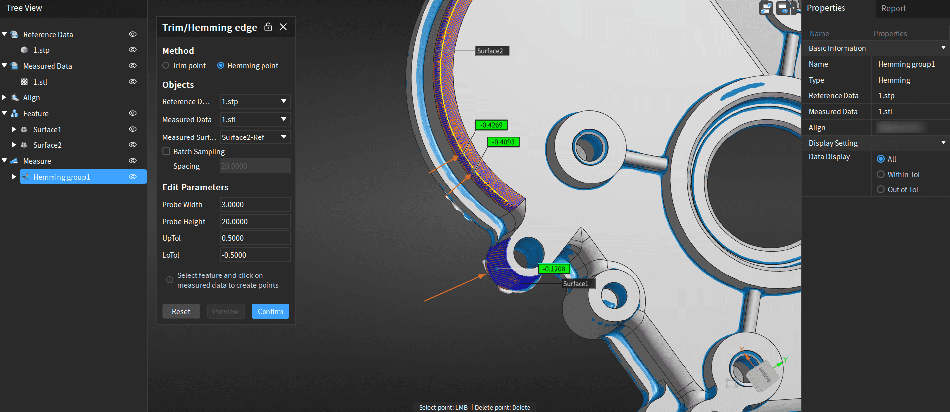
Trim/Hemming Edge Measurement
This function can be used to measure the trim edges or hemming edges of sheet metal parts.
Note
Before using this function, you need to import the reference model and measurement model, and create surface features.
- In the measurement toolbar, click
 Trim/Hemming Edge Measurement to open the corresponding window.
 - Select the detection method as Trim Edge or Hemming Edge.
- Select the reference model, measurement model, and measurement surface.
-
Edit the parameters.
Parameter Value Range Sampling Spacing 0 < x ≤ 10000 Probe Width 1 ~ 100 Probe Height 1 ~ 100 Upper Tolerance / Lower Tolerance / -
Click Apply to draw the trim/hemming line on the selected surface feature in the scene.
-
Left-click on the drawn trim/hemming line to generate trim/hemming measurement points.
Note
- Left-click to generate trim/hemming measurement points.
- After left-clicking to generate trim/hemming measurement points, press Del to delete the generated measurement points.
-
Click Confirm to complete the detection, and the measurement item will be displayed in the
measurement module in the left directory tree.
Note
- After completing the inspection, you can select the measurement points to be displayed in the data display section of the right properties panel.
- After completing the inspection, you can right-click on the trim/hemming edge measurement group in the directory tree to edit the parameters and measurement points again; the edited values will be applied to all measurement points.