Extreme Position Point Creation
Typically used when inspecting irregular workpieces that require measuring distances between two extreme positions, this function can be used to create features at extreme positions first.
Note
- The extreme position point creation method is applicable to creating point features.
- Features created by this method are reference features by default, so before creating features, please import a reference model; if measured features need to be extracted, a measured model also needs to be imported.
Creation Steps
Col
- Select
 Extreme Position Point in the drop-down menu of
  Point.
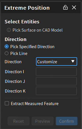
 - Click on the approximate surface where the extreme position point needs to be created on the reference model in the 3D scene as the calculation area.
- Select a direction in the Extreme Position Point window:
- Pick specified direction: custom direction (default) or select X axis / Y axis / Z axis direction.
- Pick line: Select the direction of a created line feature.
- After completing the relevant settings, click Apply to preview the feature point in the 3D scene; then click Confirm to create the new feature, and the object will be displayed in the
 feature module of the left-side tree view.
Col
Extract Measured Values
After creating reference features, the corresponding measured features can be extracted automatically or manually.
Note
Import at least one measured model before extracting measured features to generate feature pairs.
-
Automatic Extraction: Enable Auto Extraction of Measured Values via
 Settings in the upper right corner of the software interface or check
  Extract Measured Feature in the creation window. The software will automatically extract the corresponding measured feature with default parameters after creating any reference feature.
Note
If there are multiple measurement objects, please select the corresponding extraction object in the creation window; the default selection is the first measured model or the first measured model within the first measurement group.
-
Manual Extraction: After creating a reference feature, right-click the feature group in the tree view on the left, select Extract Measured Feature and specify the measurement model to be extracted; you can specify Align Object in the extraction pop-up window.
Note
When selecting sub-features, 2D features, or when there are only sub-features or 2D features in multiple selections or groups, right-click the feature group in the left tree view and select Extract Measured Feature to directly extract the measured feature without selecting a measured model.